|

|
Forum Index : Electronics : Various aspects of home brew inverters
| Author | Message | ||||
| wiseguy Guru Joined: 21/06/2018 Location: AustraliaPosts: 1156 |
Ok After a rethink I concur with a soft stop. As we had a soft start I reasoned it would take care of residual core magnetism by pulling it back into range at start up. However I agree, why leave it in that state if we can choose to leave it with minor or no residual flux with a soft stop. With regard to inductive Kick, wouldnt stopping the inverter at a zero crossing mean zero current so there should be no inductive kick back? When an inverter goes feral due to a component failure ie FET or Drive issue the resultant fireworks and damage until the breaker "pops" may be reduced if no other FETs are driven on to contribute more current to the unfolding mess. If current sense, above a certain threshold, to the bridge was fast enough to shut down all drive signals in a short enough time, in theory no further damage would result ( apart from the existing problem that caused the over current). I suspect that discrete analog circuitry may need to be employed to actually achieve this. I am unsure of the timing involved in the micro from sensing the EEK input to shutting down drive outputs - it does not have to be used at all, I just considered if it was there for further development (to play with) maybe we can achieve better results for serious faults/failures ? Mark can you shed some more light on the over current scr latch setting on your inverter. I know it is related to AC load and there are also usually AC circuit breakers for continuous overload. What AC current level setting actually triggers it into shutdown. I know drop saws and the like are almost a short circuit for the first revolution, so what compromise is used between false tripping and no trip ? If at first you dont succeed, I suggest you avoid sky diving.... Cheers Mike |
||||
| poida Guru Joined: 02/02/2017 Location: AustraliaPosts: 1418 |
Wiseguy, I read you as wanting immediate stop, at any time in the waveform, for very bad situations. And normal stop events were to occur on zero crossing. No problem. Once we all come to some decision, we can put this issue to bed. wronger than a phone book full of wrong phone numbers |
||||
| poida Guru Joined: 02/02/2017 Location: AustraliaPosts: 1418 |
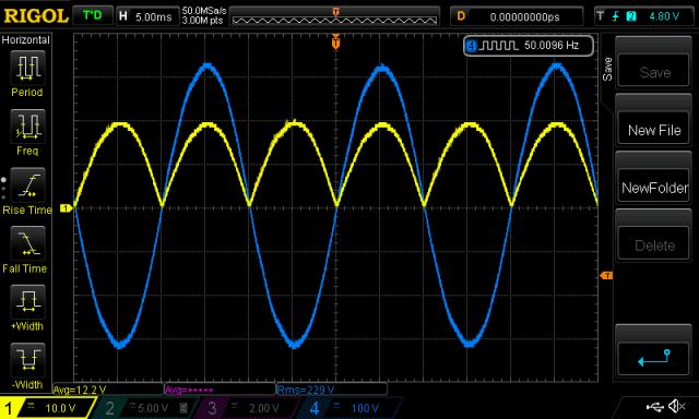
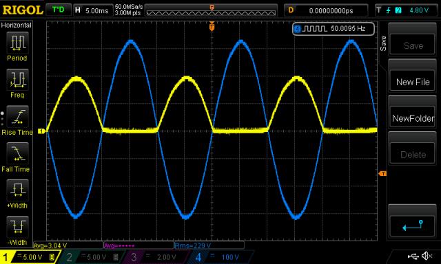
Tinyt: the AC to be sync'd signal is sent through a full bridge rectifier. It gives a rising edge interrupt each 1/2 cycle. I don't like there is no way to tell which 1/2 cycle caused the interrupt. The nanoverter will sync at randomly chosen times 0 degrees and 180 degrees with respect to the AC sync input. If you use a single diode then things become feasible. There is one rising edge only every full cycle. full bridge:  single diode:  wronger than a phone book full of wrong phone numbers |
||||
| wiseguy Guru Joined: 21/06/2018 Location: AustraliaPosts: 1156 |
Sorry Poida, we were talking crossed purposes, normal shutdown vs EEK. Yes EEK was to stop it dead where ever it was & normal shutdown at zero cross - but now soft stop. Which is the lesser of 2 evils - proceed to fireworks or shutoff the FETs instantly & hope the internal FET diodes take care of the back EMF - I choose option 2 lol. If at first you dont succeed, I suggest you avoid sky diving.... Cheers Mike |
||||
| tinyt Guru Joined: 12/11/2017 Location: United StatesPosts: 438 |
OK, now I understand. Attached schematic for review now has a single diode.2018-11-19_114141_NANOVERTERdraft4.pdf |
||||
| poida Guru Joined: 02/02/2017 Location: AustraliaPosts: 1418 |
Tinyt: I have sync working now, with breadboard single diode sampler. There is so much noise on this input to pin D2. I placed a 22nF across it to ground at the pin input. see the video first I hold reset to show no sync. Then the code runs and is on standby. While on standby, the sync code aligns output to sync pulses Then I press ON, for AC output. This sometimes upsets the sync but it is regained. There is a small phase error, this is a puzzle to explore later. Yellow is pin D2 input White is my street power Light Blue is inverter AC output. My Uno seems to have clamp diodes of about 7V. additions.. setup: EICRA &= ~(bit(ISC00) | bit (ISC01)); // clear existing flags EICRA |= bit (ISC01); // set wanted flags (falling level interrupt) EIMSK |= bit (INT0); // enable it int_f=0; the interrupt.. ISR (INT0_vect) { if (int_f == 0) return; // only once per 50 Hz cycle. Noise! much noise... int_f = 0; pcint = pcount + 200*v1low; // get position in 50Hz waveform, 0 - 400 if (pcint < 200) // servo around 200 counts, 1/2 way in waveform { if (pcount < 399) pcount++; // do not overflow sine wave lookup table } if (pcint > 200) { if (pcount > 0) pcount--; // and do not underflow. } } and an addition to timer1 overflow.. if (v1low == 1) { .. int_f = 1; } else { ... wronger than a phone book full of wrong phone numbers |
||||
renewableMark Guru Joined: 09/12/2017 Location: AustraliaPosts: 1678 |
It's adjusted via a trimpot. Once the machine is up and running the pot is centred, then power some max loads you intend to run, if it trips then adjust the pot higher. Can't remember exactly but recall running house AC, a blow heater, and started a compressor and mitre saw via a double adaptor while the others were running already. Then started placing even more load to make it trip just to see where it was actually going to trip. Having that in the circuit doesn't look like many extra parts. So if you add a DC breaker on input and an RCBO on output then you have 3 current related safety features all contained in the box. But none will save the fets if a problem arises, however no blown up boards or fires either. Cheers Caveman Mark Off grid eastern Melb |
||||
| tinyt Guru Joined: 12/11/2017 Location: United StatesPosts: 438 |
Awesome, thanks poida. Maybe the phase error is due to the 2.6v input threshold voltage of DIO pin D2. If the AC voltage at the anode of the diode is higher, maybe the phase error will be smaller. But circuit values need to be adjusted. If the AC voltage is too high, we might need a zener diode to protect the DIO pin D2. Will study your code later. Thanks again. |
||||
| Mulver Senior Member Joined: 27/02/2017 Location: AustraliaPosts: 160 |
Does this work if the sync signal is removed and then later returned without turning off inverter? |
||||
| poida Guru Joined: 02/02/2017 Location: AustraliaPosts: 1418 |
yes. No hiccups wronger than a phone book full of wrong phone numbers |
||||
| poida Guru Joined: 02/02/2017 Location: AustraliaPosts: 1418 |
OK, I have decent working code now. It can obtain sync from any freq from 50.12 to 49.88 Hz Probably need a bigger range than that. Later as needed. It drives pin D4 high when in sync, low when out of whack or no sync pulse present. The inverter runs irrespective of sync presence or lock. D4 can drive a relay to connect/disconnect the inverter to the synchronous master circuit. 2018-11-19_153427_nano_1_v2.ino.zip Yellow is pin D4, no sync is low, in sync is high (5V) white is street power (actually, inverter power, we have sun in Melbourne!) light blue is inverter AC output. I let it run for a little, then switch out the sync, and the yellow line drops to zero, the two waves go out of sync, then I switch it back in, sync is reestablished and the yellow line goes high. yet another video wronger than a phone book full of wrong phone numbers |
||||
| Tinker Guru Joined: 07/11/2007 Location: AustraliaPosts: 1904 |
Neat, I like it. A curiosity question poida; what is the 50Hz frequency output referenced to? I measure 49.91Hz (using an earlier code of yours) and wonder if its my meter or what? Not that such a small difference matters with a stand alone power system. Klaus |
||||
| Clockmanfr Guru Joined: 23/10/2015 Location: FrancePosts: 429 |
HZ stability does matter. My experiences with drifting HZ. The main reason I fell out with Inverter manufacturers that use upping HZ to act as a control when AC coupling. To me HZ increase is just stupid or are those manufactures just lazy. Some Domestic appliances, ie Washing machine, tumble drier, have synchronous timers, and things like a microwave turntable have a synchronous motor drive. At 54HZ the timers on washing machine timers will not run correctly and the synchronous motor on microwaves sound like a bag of nails in a tin. At 52Hz stuff works okay, but even then a synchronous motor will not be happy. Everything is possible, just give me time. 3 HughP's 3.7m Wind T's (14 years). 5kW PV on 3 Trackers, (10 yrs). 21kW PV AC coupled SH GTI's. OzInverter created Grid. 1300ah 48v. |
||||
| Tinker Guru Joined: 07/11/2007 Location: AustraliaPosts: 1904 |
Well, yes and no. I was commenting about 0.1Hz less than 50Hz. This is quite stable, I measured always the same difference over several days. Klaus |
||||
renewableMark Guru Joined: 09/12/2017 Location: AustraliaPosts: 1678 |
If it can be made to have a genset plugged in and backfeed charge like the GTI's can with the OZ/Mad inverters that would be a serious game changer for people running entirely off grid. Currently my options are, run a gen and use a 48v charger, but they are fairly pricey in large amp capacity, the one I have will do 20A @48V, which is pretty small, just under 1000w. If it was possible to plug in a 3000-4000w gen and backfeed charge that, it would be marvellous. That would be enough to get the bulk charge done on a cloudy crap day (keeping an eye on it of course). Occasions like this would be limited to perhaps a few times a year to maybe a few dozen, depending on batt capacity and panel capacity, and load. I have in the works a diesel motor which was planning to run PMA's off it to charge the battery bank, that's a very specific one purpose bit of kit(which will be a lot of frigging around to get right). A plug in gen set option really would be awesome. And just peace of mind for totally off gridders. Having that option there then which is reasonably affordable and available would be awesome, nothing out there can do this as far as I'm aware. Cheers Caveman Mark Off grid eastern Melb |
||||
| wiseguy Guru Joined: 21/06/2018 Location: AustraliaPosts: 1156 |
Good work TinyT, not sure why but are some of the bussed connection lines invisible or they are not meant to be seen ? ie OC1A and OC1B pins from the micro appear to join an invisible buss? Are VB & VS on U3 & U2 meant to be linked to share the bootstrap parts (same for U5,U4). Or is having the same net name all that's required. Also the Net on the connector J3 for 2VS is mislabelled as VS2. Comment, the IR2184 has ~ 500nS deadtime the IR21844 has 400nS - 5uS - I see its main advantage is winding back deadtime to 400nS I cant imagine ever needing more than 500nS - in my past experience anyway. If at first you dont succeed, I suggest you avoid sky diving.... Cheers Mike |
||||
| tinyt Guru Joined: 12/11/2017 Location: United StatesPosts: 438 |
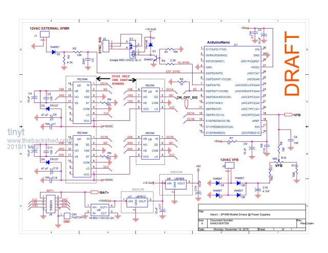
I checked the pdf and the bussed connection lines look good to me. I am using Orcad 16.3 schematic capture (old like me). When it creates a net list for PCB layout, it uses the net name of the connection i.e. OC1A, SD, VB, BAT+, +5V, etc. If a connection has no net name it creates its own to complete the net list. The buss symbol is not used for net list creation and is just a visual aid for me instead of just leaving a connection end hanging. Yes, in the schematic the intent is for all net names like VB to be connected together. Very often I make a mistake like EXT_SYNC and EXT-SYNC, they will not be connected in PCB layout. There is a Design Rules Check tool, but sometimes I forget to do it. Somebody mentioned using IR21844 instead of IR2184, so the schematic supports both. Just make sure they are not mixed on the board. Here is updated schematic for review/comment. 2018-11-20_020531_NANOVERTERdraft5.pdf I have added a relay driven by the nano D4. The ribbon connector pin 6 net name is also corrected, thanks wiseguy. Here is jpg also to compare with the pdf.  |
||||
| poida Guru Joined: 02/02/2017 Location: AustraliaPosts: 1418 |
According to the frequency counter of the DSO, it's 50.002 Hz. I have a function generator with good accuracy and both the FD and DSO agree to 3 decimal places. I obtain this 50.002Hz by using #define PPWM 799 at the top of the code. If 800 is used, then the freq is 49.939 Hz. Maybe you are using that value? Tinyt would use PPWM = 665, to produce 60.062Hz The crystal oscillator on the Uno is very stable short term. Long term it's probably very good ("very good" might be correct to 3 decimals), I have not characterised it. Other people have: http://jorisvr.nl/article/arduino-frequency Here he shows the board he has (a different model, but using the same sort of crystal) has an error of 0.011% of it's 16MHz. i.e. 16MHz is measured by his good gear as 16001679 Hz We can choose the best value for PPWM to get the desired 50Hz. The above link is good reading for the question of nanoverter's AC output frequency. Another project of mine is logging the mains frequency in Melbourne. I record data every 2 seconds. The system gives me easily enough accuracy when fed a clean trigger source (4 decimals from memory) But I have no clean trigger source: I have mains power. have a look at this which shows all of 19th Nov frequency data. The bottom graph is 24hrs, the top is zoomed in data from the small rectangle. Mains power frequency has much short term variability, within a range, but it has very good average long term stability. That is why we can run clocks off it. If I graphed the nanverter output, we would get a straight line. If you want to explore this data to look at other days, the url is http://smtp.bqdesign.com.au:81/freqlog/f5.php?ddate=20181119 It takes a while to load...then choose a different day. And wait... wronger than a phone book full of wrong phone numbers |
||||
| poida Guru Joined: 02/02/2017 Location: AustraliaPosts: 1418 |
Tinyt: thanks for the schematics. I would like to add a small thing, a jumper to connect D2 (INT0) to ground. This is to most certainly and under all circumstances prevent sync pulses entering the uC. The jumper will be the enable/disable sync control. Could I have also, a note "C3 to be mounted close to U1 pins 4,5"? C8 might also be placed close to pin 19 (ADC ch0) with advantage. What do you think? There is incredible amounts of high frequency noise near inverters. Maybe a LED to show sync status? This is up to you, I don't mind. wronger than a phone book full of wrong phone numbers |
||||
| Solar Mike Guru Joined: 08/02/2015 Location: New ZealandPosts: 1138 |
Poida, it adds to complexity but a decent low pass filter on all CPU ADC inputs has a number of advantages, (1) removes all noise, (2) presents a very low impedance source for the ADC and any subsequent other monitors of the voltage value. I don't bother measuring mains volts via a transformer anymore, just sample the battery volts instead, these inverters are so over spec'd that the core has extremely good regulation, so mains AC voltage is a direct reflection of the battery value. Cheers Mike |
||||