
|
|
Forum Index : Electronics : Builiding of a complete 6kW PV inverter with MPPT chargers
| Author | Message | ||||
| wiseguy Guru Joined: 21/06/2018 Location: AustraliaPosts: 1008 |
Not familiar at all - way too neat, they look like commercial units.  Good job Mat, a very high quality build, you must be pleased with the results too. When is the big MPPT test - how many strings of Panels do you have at present ? If at first you dont succeed, I suggest you avoid sky diving.... Cheers Mike |
||||
| -dex- Regular Member Joined: 11/01/2024 Location: PolandPosts: 46 |
Thanks. MPPTs hasn't been tested yet. Let's hope it doesn't turn out to be expensive commercial fireworks  Now I have 3 strings in a 3s2p arrangement. Open circuit voltage ~110V, at maximum power (2.5kW) the voltage drops to approximately 90V - this is what the datasheet says, but it will be verified soon. |
||||
| -dex- Regular Member Joined: 11/01/2024 Location: PolandPosts: 46 |
I placed the LCDs on a piece of plexiglass. They are supported by nano controllers placed on adapter boards. 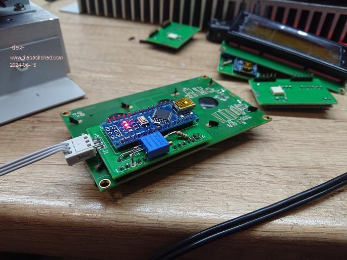 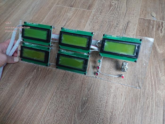 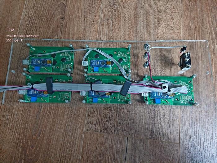 |
||||
| -dex- Regular Member Joined: 11/01/2024 Location: PolandPosts: 46 |
First serious bang bang! So far, for testing purposes, I have used a set of 4 small AGM batteries as a power source. The inverter has been pre-started, so there is no chance of any wiring errors. Today I installed the target set: 16pcs of lf280k cells. The links were pressed together using two sheets of metal and screws. The voltage of the entire battery pack was 53V. Everything looked OK. I switch onthe MCCB breaker that supplies voltage to the busbars to the system and at that moment there was a huge flash, a beam of sparks from the cell, I realized that it was a short circuit and immediately disconnected the fuse. How did this happen? I don't know. But I found out how dangerous these small, inconspicuous blue boxes are. 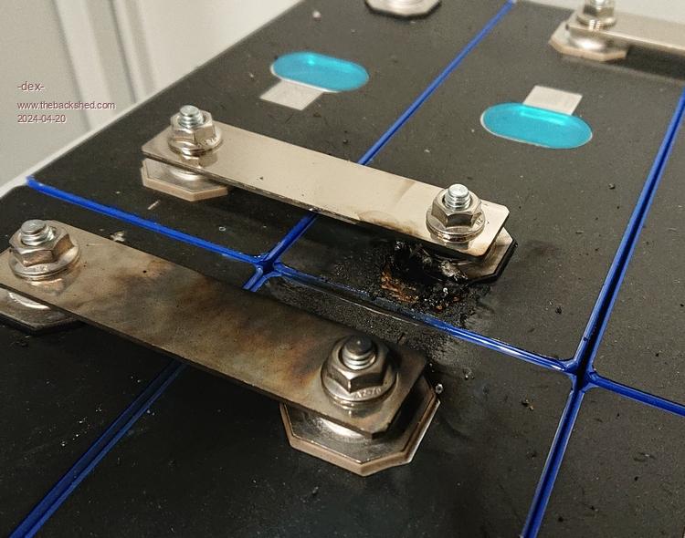 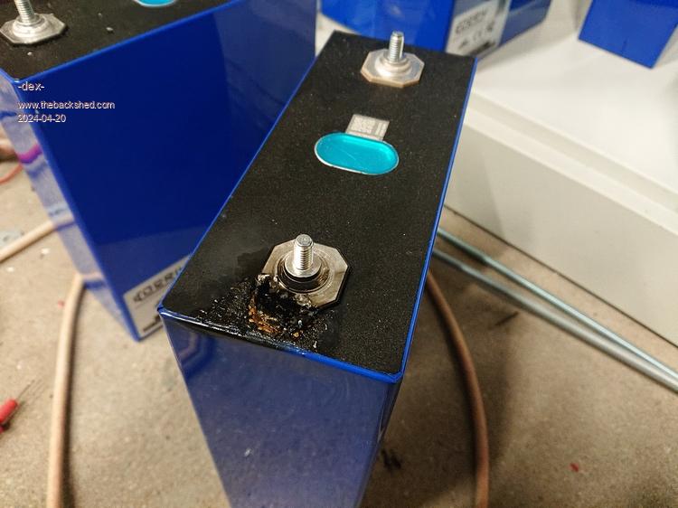 |
||||
| -dex- Regular Member Joined: 11/01/2024 Location: PolandPosts: 46 |
After this accident, I checked whether the "+" and "-" buss were shorted behind the switch. After MCCB breaker there is no short circuit. I can only add that the negative busbar is connected to ground, and the entire housing is also connected to the ground busbar. In other words, the entire case has a "-" battery potential Is it possible that the short-circuit current flowed through the cell housing into the system housing? I didn't use any additional spacers/separators. I dismounted battery pack and it turned out that some of the cells were slightly injured and could have come into contact with the metal screw, and then screw with metal housing. I further checked whether the cell's aluminum casing had any potential under the blue foil. It turns out yes. Some of them have "-" on the housing, and the rest have "+" on the housing. However, it is not a full connection with the terminals, there is some resistance between them. 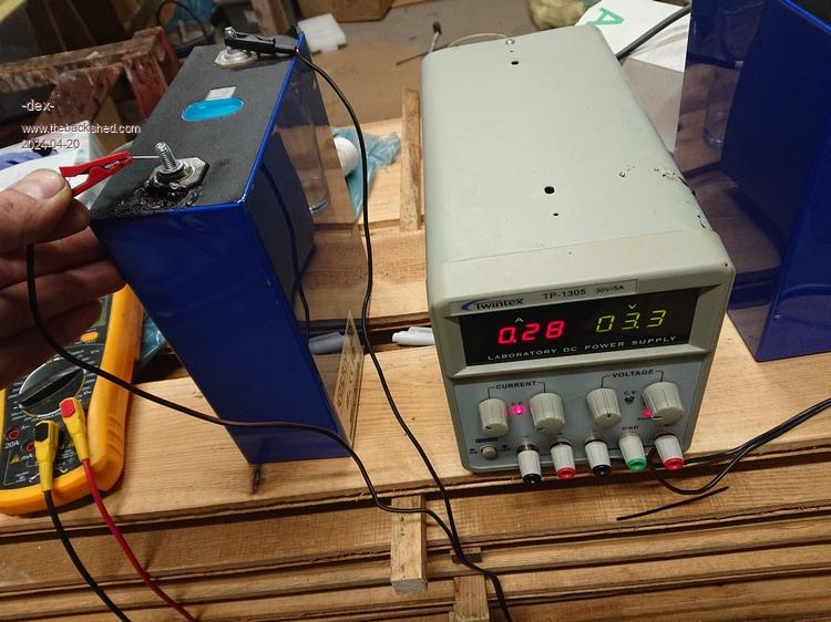  |
||||
| rogerdw Guru Joined: 22/10/2019 Location: AustraliaPosts: 809 |
Ouch, that would have given a fright. Sorry I have no experience with those cells at all. I have read of some types where there is concern about the insulation on the outer battery case being too thin or being damaged and causing issues. It's always nervewracking switching things on the next time after a blowup ... well it is for me anyway ... so good luck when you fire it up again. Your mppt chargers turned out really well too, congratulations. I plan to fit my displays and some analogue meters like that to the front cover ... when I get to that stage. Cheers, Roger |
||||
| Murphy's friend Guru Joined: 04/10/2019 Location: AustraliaPosts: 592 |
I do not think it is a good idea to ground the battery negative to chassis. I certainly do NOT do that in my inverters. Instead I connect the AC ground to the chassis/housing. That way there is no bang if one of your battery leads accidentally touches the housing cabinet. |
||||
| analog8484 Regular Member Joined: 11/11/2021 Location: United StatesPosts: 92 |
Any large lithium battery can cause havoc quickly due to the much lower internal resistance compared to lead-acid/AGM batteries. I also learned the hard way. I second Murphy's suggestion. |
||||
| KeepIS Guru Joined: 13/10/2014 Location: AustraliaPosts: 1392 |
The aluminum case is normally at one potential- some brands cells normally come with a type of fiberglass spacer sheet, can be bought in packs if you have nothing suitable, these protect close mounted cells, a 54v LifePO4 battery bank is seriously extremely dangerous. That looks like a breakdown between the case and the opposite polarity terminal. That should not happen. Shorting out a 54v bank normally vaporizes the object causing the short or cable. Did you have a BMS connected - that's one of the things it's meant to stop- total battery destruction with almost unlimited current available in the event of a external short. It's all too hard. Mike. |
||||
| Solar Mike Guru Joined: 08/02/2015 Location: New ZealandPosts: 1128 |
That would give you a fright! With these type of battery cells the blue shrink wrap insulation is not sufficient to prevent cases shorting; always place an insulator like thin glass fibre sheet or thin polycarbonate sheet between all mating cell housings and the bottom if sitting in a metal box. That splat looks like between the case and terminal, wow something wrong possibly in that cell or the case was touching another. |
||||
| phil99 Guru Joined: 11/02/2018 Location: AustraliaPosts: 1805 |
If the base of that cell was in contact with the metal shelf then the connection between the terminal and the case would blow like a fuse. Check the base of that cell for damage to the blue skin. If that is what happened it is possible that cell can still be used if the cells sit on plastic. |
||||
| -dex- Regular Member Joined: 11/01/2024 Location: PolandPosts: 46 |
Yes, the blue insulation is damaged. This is a small damage and there is no trace of high current flow, nor is there any trace on the screw. If there was a knocking surface, it was not large considering the current that flowed. I'm not sure if I want to continue using it. This short circuit didn't make much of an impression on cell - the voltage dropped by less than 100mV. However, there is a hole from which some liquid leaked. 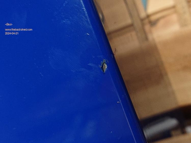 |
||||
| -dex- Regular Member Joined: 11/01/2024 Location: PolandPosts: 46 |
The inductance of the first chokes (2x 10uH) turned out to be too low. I went the other way and wanted to check what would happen when the inductance will be much higher than required. This 10kg choke is originally rated at 250uH/200A. So I disconnected the two series windings and obtained two separate coils of 125uH each.   Connection diagram as in the diagram below.  No-load waveforms has obvious distortions. The ripples are not noticeable. A resistive load reduces the wave shape to a perfect sinusoid, while all other types of loads cause very strong wave deformations.     I also connected other loads, and the wave deformations are very deep. |
||||
| KeepIS Guru Joined: 13/10/2014 Location: AustraliaPosts: 1392 |
Yes, that is exactly what will happen when you go much above a total of 60uH with a decent toriod transformer. All of my testing has always been skewed towards the bigger heavy complex loads - that is where the Inverter has to survive. Things can look sweet with a good restive load of a few kW, but the inverter can fall in a heap with complex load conditions, I never have any large resistive loads running on the system when testing, that can hide and dampen some bad shi!. . It's all too hard. Mike. |
||||
| -dex- Regular Member Joined: 11/01/2024 Location: PolandPosts: 46 |
I go back to the EMS cores and re-wind them as shown in the photo. This white tape is a 0.19mm thick Mylar film cut from a large sheet. Unfortunately, to accommodate the required number of turns, I placed not two, but one layer of copper tape. With my maximum loads up to 150A, which usually do not last longer than 10-15 minutes, this means an increase in the temperature of the copper tape by about 20 degrees. No I have 2 x30uH and the saturation current is somewhere around 160A. So this chokes will continue to be tested and closely watched. The waveforms looks very good. Changes in the waveforms under load are not as drastic as in the case of 2x125uH, although they are also visible. So far I've only caught waves at no load. Even though the choke is glued and fastened with clamps, it makes a squealing sound during operation, which gets louder and louder when I load the inverter.    Edited 2024-04-29 20:00 by -dex- |
||||
| -dex- Regular Member Joined: 11/01/2024 Location: PolandPosts: 46 |
Due to the lack of a target battery and concerns about extensive damage, for testing I run the system on a set of small 4x7ah 12V batteries, 48V in total. I also already have an ATS switch installed in the main electrical board. I have made many attempts to switch the house from the grid to the inverter and vice versa, it works fine. The nano controller's "mains relay" relay supplies 230V voltage to a large contactor which, after soft-startup, supplies voltage to the main electrical board First problem with MPPT circuit I initially calibrated and launched the first MPPT module. It works and charges well. So I left the inverter and MPPT on while it was sunny for a few hours, the load was all light 500-1500W on a Saturday afternoon. Due to the tiny batteries, the voltage on them dropping quickly under bigger loads, so the inverter turned off via UVP (low battery voltage) protection. The battery charged up, then the inverter restarted, and when ATS switched the house to the inverter, I heard a small BANG BANG and a flash from under the MPPT board - so the MPPT was damaged and now has a short circuit at the SOLAR IN input. The explosion occurred at exactly the same moment as the house's ATS switched from the grid to the inverter. MPPT mosfets and diodes are shorted. Do you have idea what was wrong? My MPPT set-up looks like this: *Choke is 180uH (~60A calculated saturation current) *fets are FDH055N15A x3 *diodes S30TC15T-5000 x2 *PV open-circuit voltage, at full sunny is 110V. *PV pwr 2,5kW * caps 9x EPCOS 1000uF solar side, 4x1000uF on output, each cap is 300V rated and has ~65mR ESR Is my diode good for this circuit? shins04528_1-2282124.pdf Edited 2024-04-30 00:30 by -dex- |
||||
| wiseguy Guru Joined: 21/06/2018 Location: AustraliaPosts: 1008 |
I am currently looking into this problem, I have a question about your MPPT Dex, were both diodes dead or just the one package ? It appears that reverse recovery combined with high forward current (greater reverse recovery charge to remove) can lead to diode stress and failure. There are limited options to deal with this but I am still reading up about the issue. At the instant the inverter connected to the house maybe the droop of battery voltage requested higher current from the MPPT and it responded rapidly killing the diode, perhaps the nano reacts too quickly and a change in PWM could be more gradual but that might just mean we are putting off the inevitable unless the Nano over reacted and called for excessive drive for a few cycles. More investigation is needed to solve this. If at first you dont succeed, I suggest you avoid sky diving.... Cheers Mike |
||||
| Solar Mike Guru Joined: 08/02/2015 Location: New ZealandPosts: 1128 |
If I'm reading the data sheet on those diodes correctly, each internal diode in the pair is rated at IO/2 or 15 amps, so 30 amps per device; you have 2 devices in parallel. The big BUT here is that internal diodes in a package share current equally, BUT not so for separate devices; a sudden high current surge could result in one device being overloaded as current is not shared, resulting in cascade failure of the 2nd device, followed by the mosfets. The peak current though the diodes is the combined load + the inductor ripple current, so could be 52 amps + 15A ripple depending on the inductor under DC load. I suggest you get some devices with 60A or higher rating. Example Cheers Mike Edited 2024-04-30 11:32 by Solar Mike |
||||
| wiseguy Guru Joined: 21/06/2018 Location: AustraliaPosts: 1008 |
The full diode specs for the S30TC15T data sheet are a bit light on but give a spec of absolute maximum of 30A per diode for a 50Hz repetitive sinewave. They also give an absolute max spec (non repetitive) of 300A for a single 50Hz conduction cycle or for 650A for a 1mS conduction cycle. A similar Vishay 2 x 15A Schottky diode has a repetitive 5uS rating of 1000A So if we operate under the absolute Max the diode should easily have a 50A-100A per diode capability for the extra nano seconds until the other Device turns on. From my interpretation of the specs I do not believe this is a current sharing issue that is killing the diodes. I have a few papers on this issue but Qrr is often not quoted for power Schottkys. Here is an Infineon discussion on Hard switching of high speed diodes. Infineon-Power_MOSFET_hard_diode_commutation-AN-v01_00-EN (1).pdf Replacing the lower Diode with a FET is also a bit tricky for high load currents where the converter is in CCM. The timing required to switch the lower FET off before the upper series FET turns on but not letting the diode conduct in between whilst also avoiding shoot through sounds like a bit of a can of worms. The patent paper that Poida pointed to a long time ago is about a synchronous bottom FET in a series opposed configuration (for AC or DC use) that seems to overcome body Qrr effects. Although some sources say a Schottky has no reverse recovery time, Power devices do have a finite Qrr time. I think the answer might be to use a suitably rated Silicon Carbide diode that does not have any Qrr and although a single device may be ~$15AUD each in the scheme of things and if it provides better reliability a small cost. Going to a larger Schottky Diode ie 2 x 30A may or may not stop the failure but if it does it will possibly be because the larger silicon Junction can better absorb the high current spike that will still occur during the diode reverse recovery time. Supposedly a snubber to absorb most of the initial current flow for the Qrr time could also help but it smells like a lot of wasted snubber energy. How many builders of the back shed MPPT have actually had Diode/FET failures. Was the device Dex mentioned a genuine or a genuine fake with the right part number ? What rated outputs are typically used and what diodes are in other builds, maybe there are other solutions/choices ? (That work) Edited 2024-04-30 12:15 by wiseguy If at first you dont succeed, I suggest you avoid sky diving.... Cheers Mike |
||||
| -dex- Regular Member Joined: 11/01/2024 Location: PolandPosts: 46 |
Only one package is dead, it means both diodes in single packet are shorted, and only one mosfet is shorted . The diodes come from a reliable shop, there is no way they are fakes. Edited 2024-04-30 16:40 by -dex- |
||||
