
|
|
Forum Index : Electronics : Builiding of a complete 6kW PV inverter with MPPT chargers
| Author | Message | ||||
| rogerdw Guru Joined: 22/10/2019 Location: AustraliaPosts: 809 |
That's a shame. I remember the first time I found a transformer with aluminium wire and I was shocked. Felt ripped off because it's like they purposely colour the enamel to make it look like copper. It's looking good and I'm slowly warming to the idea of using varnish on all the windings. I've rarely seen any transformers I've unwound that had any epoxy resin ... so I just wound mine as neatly and tightly as possible. I guess it has two advantages ... adding to the insulation value ... and preventing buzz and hum. I did wonder if it contributed to heat build up ... but there are plenty of them out there working perfectly now ... so shouldn't be any issue. Besides most of the early SMA toroids were fully encapsulated and they were reliable enough. I think my biggest concern was if I did it wrong and had to unwind it ... then I was stuffed. Of course, now that it works I think I probably should have.  Cheers, Roger |
||||
| Murphy's friend Guru Joined: 04/10/2019 Location: AustraliaPosts: 592 |
Good point Roger, all of my early transformer windings were epoxied, mainly through the hole to hold the wire pushed out while I had a split PVC tube clamp inserted. That worked a treat to get maximum hole space but it got me when the time came to unwind and modify the winding (as in the primary of my big warpverter tranny I have now re wound). The wire was re usable but I had to pull my straightener along lots of times to remove any sharp epoxy remnants. I now have inserted a permanent split PVC tube clamp inside and a varnished rope wrap outside. This still allows good cooling while preventing wire hum. |
||||
| -dex- Regular Member Joined: 11/01/2024 Location: PolandPosts: 46 |
The third layer is already winded. I left some empty space in the first layer so that it could fit in the next layer. It turned out that the second layer was tight and the empty space was not used, similarly in the third layer. I measure the voltages on each winding and they are identical. The 40W serial bulb does not light up at all, it does not flash even during turning on. My clamp meter cannot measure such a small iddle current. It is possible to turn on the transformer without a light bulb and most turns it on without tripping the B16 fuse.  |
||||
| -dex- Regular Member Joined: 11/01/2024 Location: PolandPosts: 46 |
I'm finishing the transformer. I added a small NTC temperature sensor. The first mistake also happened - I accidentally ordered the wrong cable for the primary winding. There is 50mm2 with 7 x solid wire, in a double rigid halogen sheath. Stiff as hell. Then finalyy I ordered a welding cable and it installed without any effort  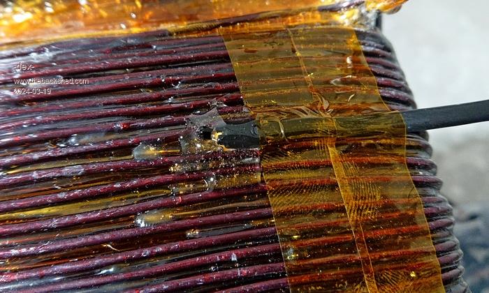 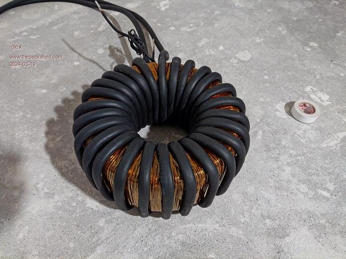 |
||||
| rogerdw Guru Joined: 22/10/2019 Location: AustraliaPosts: 809 |
That looks excellent Dex ... and you're not wasting any time either. Took me years to get mine built. That stiff wire is very difficult to handle, I can see why you ordered the welding cable. I just used some stiff 16mm wire for the chokes on my mppt and that was difficult enough. Wouldn't like to try 25mm. I missed this point earlier Klaus ... are you saying that you did this INSTEAD of epoxying the windings ... or IN ADDITION TO? I used a split pvc tube inside the large Warpverter toroid and it worked well. Just kept filing the slot a few thou' at a time and try again, until it jammed in place. Nice and tight. Cheers, Roger |
||||
| Murphy's friend Guru Joined: 04/10/2019 Location: AustraliaPosts: 592 |
Instead Roger, instead of epoxy. Epoxy is a pain if one decides to unwind that toroid but it works well for a *definitely* permanent wind. For re cycling my big toroid from the warpverter (as used in my latest inverter) I had to unwind the primary (too many turns) and while only the hole portion was epoxied it took many passes of my wire straightener to rid that 7 strand enameled wire of the epoxy remnants. You can see the inserted split PVC tube in one of my recently posted inverter tinkering pictures. On the outside I wind soft natural fiber rope which tightly constricts the windings there. That rope is then just varnished and could easily be removed if I need to change turns. Winding that rope is easy with the transformer on a turntable (as used in cake decorating). |
||||
| rogerdw Guru Joined: 22/10/2019 Location: AustraliaPosts: 809 |
Thanks for clarifying that Klaus. I was always hesitant about using epoxy for that exact reason. I rewound hundreds of motorcycle coils years ago and while I never reused the wire, the shards of epoxy were a pain and quite dangerous on some. I did use coil paint to bind them together though due to the hostile environment they had to survive in. If I ever had to do another rewind, it wasn't a huge amount of wire so no great drama. Having said that, I had hoped by keeping my turns really tight and binding each layer with mylar, that I'd avoid any major humming ... and so far it's certainly not objectionable. Tony did suggest I could contact a transformer manufacturer and have mine dipped and baked but I don't think it's really necessary. Cheers, Roger |
||||
| -dex- Regular Member Joined: 11/01/2024 Location: PolandPosts: 46 |
Thanks. Your inverter is brilliant, but it is a bit more complex for my skills. I hope to finish mine within the next month  Edited 2024-03-20 18:22 by -dex- |
||||
| -dex- Regular Member Joined: 11/01/2024 Location: PolandPosts: 46 |
Housing The inverter, chargers, batteries and protection devices will all be placed in one steel housing with dimensions of 180x90[cm], closed with a key-operated door. It is made of thin sheet metal, so it requires several reinforcements and holders to which I can mount electronics and accessories. I'm not a professional welder so it's not perfect, but it should be durable. The painted casing is now drying and waiting. 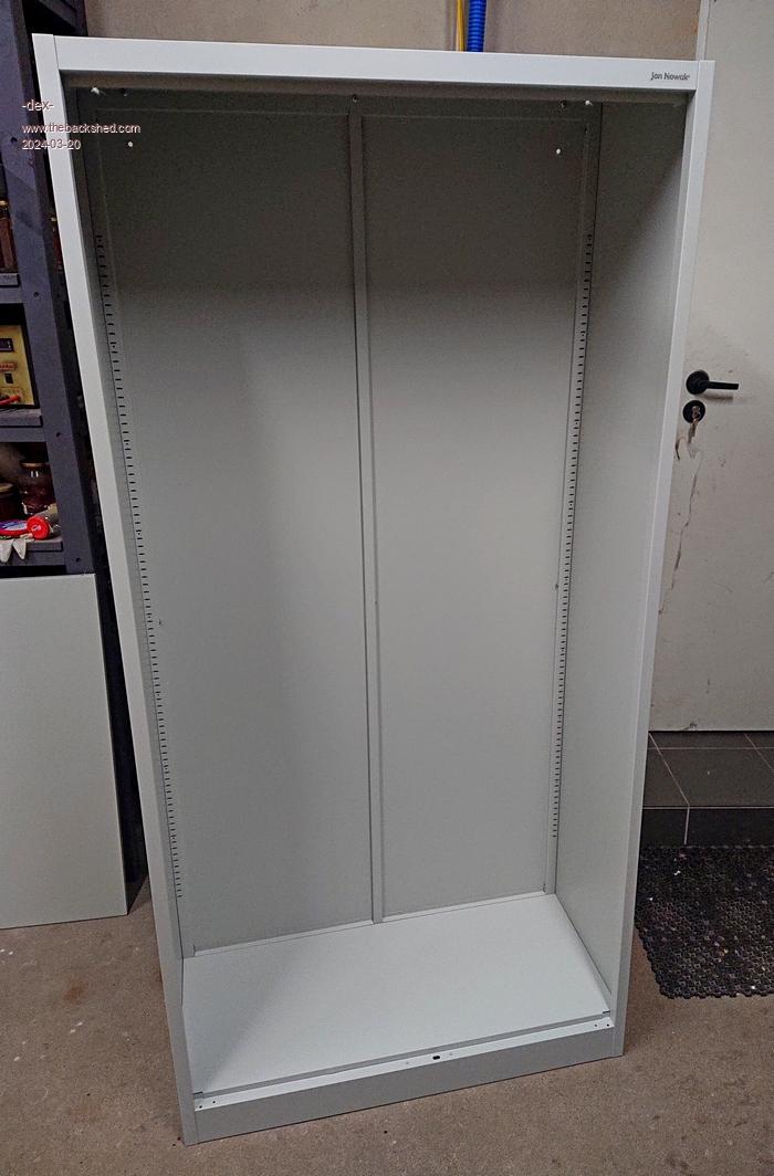 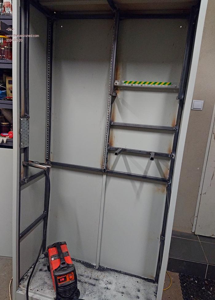 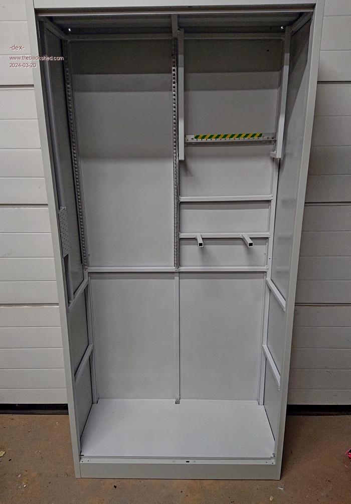 |
||||
| -dex- Regular Member Joined: 11/01/2024 Location: PolandPosts: 46 |
Inverter choke A core made of Sendust material, E type from Micrometals, mix 040 was used. A copper tape was selected for winding, dimensions 0.3x34mm, two in parallel. The measured value is 10uH, there is no more place for more. Estimated saturation current is ~300A and their saturation is not sharp but relatively soft. Made two such chokes, use in serial with toroid each leg. Used bits & core datasheet chK_core.pdf 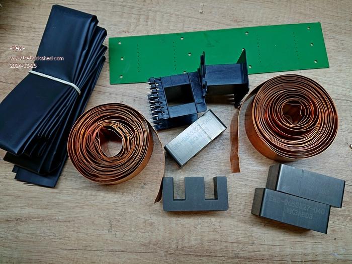 |
||||
| nickskethisniks Guru Joined: 17/10/2017 Location: BelgiumPosts: 422 |
looking great  Were did you find those cores? I my search I came up with this site, they do have lots of stuff I was looking for a long time, and suddenly it crossed my path do you know that feeling? https://sklep.feryster.pl/en/ Edited 2024-03-26 06:43 by nickskethisniks |
||||
| -dex- Regular Member Joined: 11/01/2024 Location: PolandPosts: 46 |
This is the exact store where I bought it, there is a lot of good stuff there  I also have toroidal cores for chokes for the MPPT system from them. Edited 2024-03-26 19:36 by -dex- |
||||
| -dex- Regular Member Joined: 11/01/2024 Location: PolandPosts: 46 |
I will mount the electronics on heatsinks that I obtained after disassembly. As for their size for cooling purposes, they are probably oversized, so I may not need to use fans. MPPTs will also get the same heatsinks model, and the whole thing will have a modular design. More photos to explain this soon. 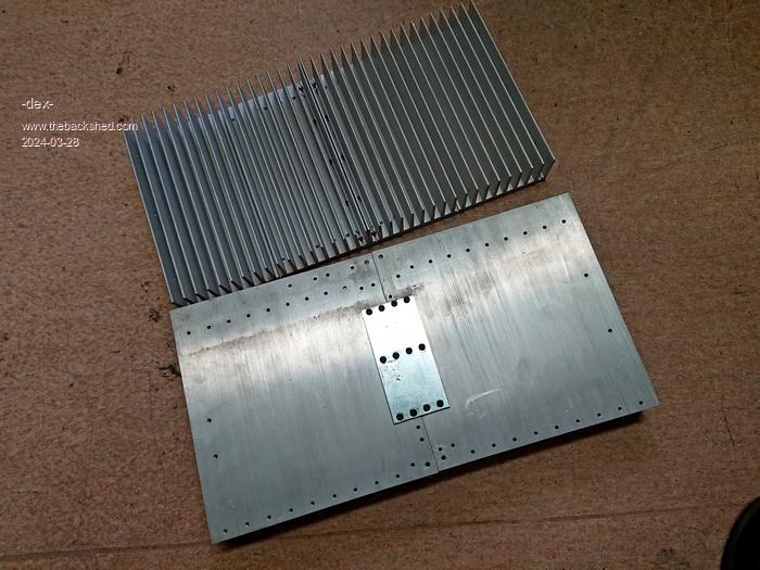 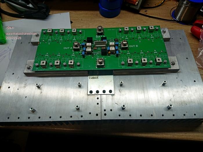 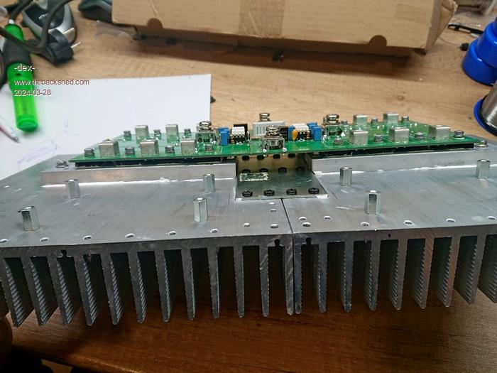 |
||||
| KeepIS Guru Joined: 13/10/2014 Location: AustraliaPosts: 1392 |
That should run fine without any heatsink fan. It's looking really good. It's all too hard. Mike. |
||||
| -dex- Regular Member Joined: 11/01/2024 Location: PolandPosts: 46 |
More photos of the work progress. The nano controller was assembled and everything was placed on the heatsink. Arranging everything in a sandwich makes the module does look like it feels packed and small. 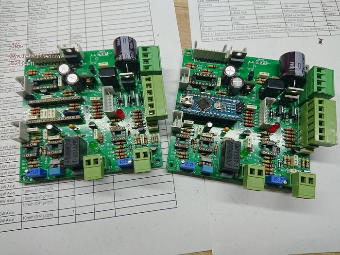 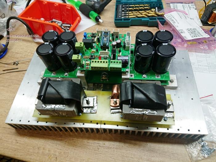 |
||||
| -dex- Regular Member Joined: 11/01/2024 Location: PolandPosts: 46 |
The inverter module has been checked and ready for first tests. Thanks to the wise instructions, the startup took place without any explosion or damage to the components. Now I need to choose the capacitor on the secondary side of the transformer. With a capacity of 2uF, the waveform has visible oscillation, but the transformer is relatively quiet. at 20uF there is no visible oscillation, but the transformer becomes noisy - a hum can be heard and vibrations on toroid are felt, and the no-load current is slightly higher. Do you have any suggestions for the capacitor? Warpseed suggested setting the resonance to 1.5x the mains frequency, but this has been questioned by some on this forum. 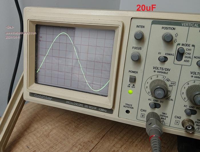 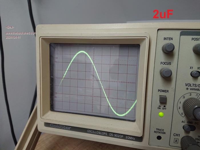 |
||||
| KeepIS Guru Joined: 13/10/2014 Location: AustraliaPosts: 1392 |
Depending on the Toriod, 3uf to 5uf - 4uf is what I ended up using. Much higher then 6uf and you start to run into problems. IMHO 2uf is too low. I tested from 2uf to around 12uf with an AC distortion analyzer - no real benefit, it only effects Idle harmonics a bit, but not distortion under load, as it's swamped by the distortion caused by the crap loads. That was true for the Inverter and for AC mains. BTW Very nice build. I'm just starting on the second controller. . Edited 2024-04-11 18:51 by KeepIS It's all too hard. Mike. |
||||
| Murphy's friend Guru Joined: 04/10/2019 Location: AustraliaPosts: 592 |
What power level do you plan to use this inverter with? The copper dimensions you gave above for the choke winding is a bit on the small side for anything over 4KW, using a 48V battery. As you seem to have glued the E core halves together, the glue might soften if the choke gets too hot. I would prefer mechanical clamping for this task. I select the secondary capacitor with the 75Hz resonance test, worked for me. You are right, the no load current is affected by this capacitor value. Suggest you try those clip on noise suppressors on your AC wiring first and add a fully shielded AC filter for good measure. That should rid your wave form of that tiny oscillation, at least at lower power levels. |
||||
| -dex- Regular Member Joined: 11/01/2024 Location: PolandPosts: 46 |
The most common loads do not exceed 4kW. Sometimes it is 6-7 kW but it lasts no longer than 10 minutes. I will check with 4,7uF capacitor. I think I have somewhere metal-shielded emi filter so also will test this, thanks. |
||||
| -dex- Regular Member Joined: 11/01/2024 Location: PolandPosts: 46 |
I assembled 4 MPPTs. Don't they look familiar for backshed members? The inductors were wound with four parallel wires, the inductance is 190uH and the estimated saturation current is around 60A. 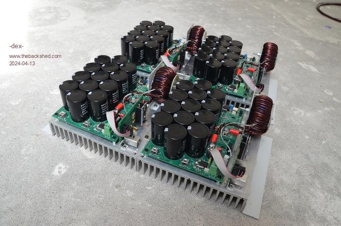 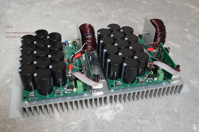  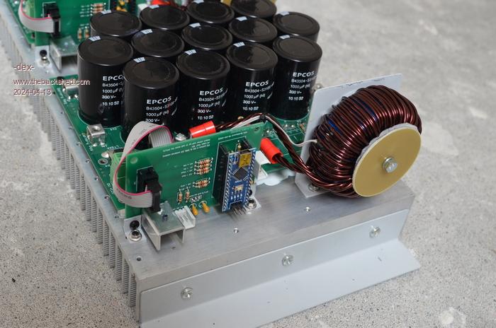 Edited 2024-04-13 22:10 by -dex- |
||||
