Notice. New forum software under development. It's going to miss a few functions and look a bit ugly for a while, but I'm working on it full time now as the old forum was too unstable. Couple days, all good. If you notice any issues, please contact me.
rogerdw Guru Joined: 22/10/2019 Location: AustraliaPosts: 809
Posted: 12:30am 20 Mar 2024
Copy link to clipboard
Print this post
Thanks very much Klaus, that would be very helpful. I'll send you a pm.
Thanks for that ... and I'm a fan of analogue meters too. They're more my speed and like you say you can see them in a glance from a distance.
I'm amazed, I had no idea of the differences between all the equipment. Been naively relying on the mains for years and never really having any problems. Big motors and pumps I suspected ... but not smps's and variacs.
Once I have a peak meter I'm hoping I'll get a lot better understanding. I've also ordered one of those small dso meters as well to leave attached to keep an eye on things.
I've learned a lot just standing watching the Warpverter and mppt displays but have a lot more to learn. I also just received one of the Juntek DC displays so I can keep a better eye on the battery condition. Slowly getting there.
Footnote added 2024-03-20 10:44 by rogerdw Hey Klaus, I did try sending a PM but it won't select your name. I reckon I've seen others say they couldn't message you either. Would you mind trying to send me one please? Thanks.Cheers, Roger
rogerdw Guru Joined: 22/10/2019 Location: AustraliaPosts: 809
Posted: 12:38am 20 Mar 2024
Copy link to clipboard
Print this post
Thanks Phil it's amazing, the longer I work at this the more I realise I don't know. I have seen all of those approaches over the years but never understood why they were being applied.
I'm keen to see what Mike comes up with to reduce the surges on various devices.Cheers, Roger
KeepIS Guru Joined: 13/10/2014 Location: AustraliaPosts: 1392
Posted: 03:02am 20 Mar 2024
Copy link to clipboard
Print this post
Rodger, the one thing to watch with the Junctek DC Battery monitors:
Do not under any circumstance disconnect the big bolt down Current Shunt Terminals with the (voltage reading) DC input connected to the Junctek "Vsns or VExt" connector.
It's a 3 pin plug, always "unplug First" and Plugin Last" when playing around with the Negative battery terminals to the shunt.
Yes a Zero crossing switch will work for some loads, if can also ramp up, it will work for almost every load, however it may be a bit more involved compared with a simple slow start circuit. . Edited 2024-03-20 13:03 by KeepISIt's all too hard. Mike.
rogerdw Guru Joined: 22/10/2019 Location: AustraliaPosts: 809
Posted: 03:30am 20 Mar 2024
Copy link to clipboard
Print this post
Thanks Mike, it almost sounds like you have some experience in that area. Thanks for the warning.
I have a lot of small jobs to do to finish off my system ... but it's looking like I should put up my last lot of panels next.
After not realising a pair of fuses were missing in my combiner box and being disappointed with the third array's output ... today I've seen the total charge current get up to 176 amps from all three combined. Adding another 12 panels should bring it up to a max of say 225 amps. Battery will love that. Cheers, Roger
KeepIS Guru Joined: 13/10/2014 Location: AustraliaPosts: 1392
Posted: 03:55am 20 Mar 2024
Copy link to clipboard
Print this post
Yes easy done, been caught before with the fuses.
IMHO you just can't have too many panels. I usually get asked me why I need so many, seems everyone forgets that the sun does not always shine, especially a certian group of mindless ops! Stop! whew! just caught myself in time...
It's amazing how much power you can generate on an ugly rainy day with a good area of panels, enough to stay off grid for a week or more if you ration things just a little and use that not so common ability - common sense
We can cut back on using equipment, use the gas bottle, keep the lights, security systems up, garage electric Panel lift doors and locks working, fridges and freezers all running and still have our cappuccino machine working twice a day, and even run one AirCon during the day, and more.
Sure beats the smell of rotten expensive food . Edited 2024-03-20 13:56 by KeepISIt's all too hard. Mike.
KeepIS Guru Joined: 13/10/2014 Location: AustraliaPosts: 1392
Posted: 04:31am 20 Mar 2024
Copy link to clipboard
Print this post
That should read a Switch to avoid power on at Zero crossing for the Variac, and other toriod transformers and larger E-Core transformer devices.
Otherwise use a soft/slow start circuit, or just use a soft start for all plug packs and any type of large transformer devices that also feeds "big" DC smoothing caps.It's all too hard. Mike.
rogerdw Guru Joined: 22/10/2019 Location: AustraliaPosts: 809
Posted: 11:24am 27 Mar 2024
Copy link to clipboard
Print this post
Well it's time for an update.
I was probably a bit too enthusiastic in using as much power as I could at the start and then after a few dull days, the battery was struggling a little. I ended up using one of my 50 amp chargers to top it up for a few hours several times, so it would last the night.
I got a bit of a fright several times when using a bigger load and the battery volts dropped low enough for the Warpverter to lose regulation and 'hunt'. And a couple of times the lights varied hugely and the fridge rattled badly when that happened ... and I took off running to turn the charger on.
That experience convinced me I needed to get more of my planned panels on the roof, so I put up the next array of 12 x 250w panels and hooked them up to MPPT #3. As mentioned in another thread, to start with I was terribly disappointed as the output was a lot lower than the other arrays of 12 x 275w ... but after finding a couple fuses missing and fitting some, the output was quite respectable.
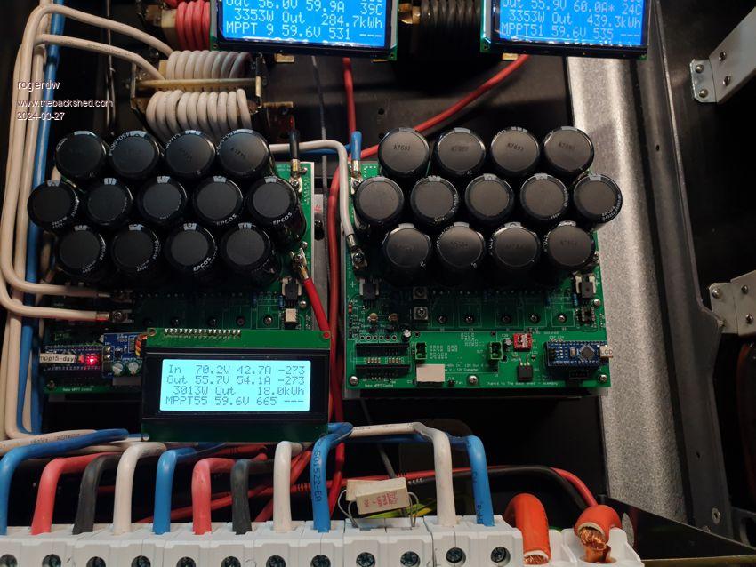
Considering these are all old secondhand panels, I've been impressed with their output. Nothing wrong with these at all. In this photo all the arrays are putting out their stated output despite their age.
On the weekend just gone I fitted the last dozen 250w panels though haven't wired them all the way through yet. When that's done there will be 12.6kW available to charge the battery.
In my next update I'll explain what's been holding me back.
Cheers, Roger
rogerdw Guru Joined: 22/10/2019 Location: AustraliaPosts: 809
Posted: 12:34pm 27 Mar 2024
Copy link to clipboard
Print this post
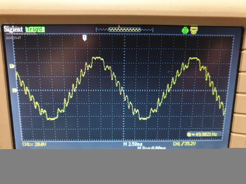
When things go wrong it can be hard to keep track of time and the sequence of events but just before the weekend I came in and the Warpverter sounded a bit noisier than usual ... and I just about dismissed it and went off when I noticed the output voltage was 248.5 volts. It's normally never over 241v.
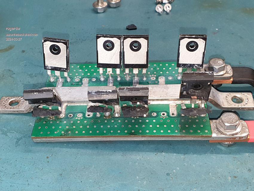
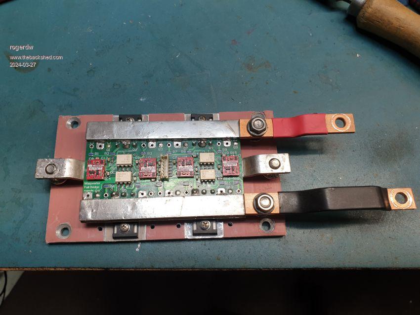
That got my attention so I grabbed my little 24v ac tx and checked the output with the dso. It was very raggedy and was clear one of the smaller inverters had failed. After shutting it down, I could see a couple of blown mosfets on the second smallest bridge ... so whipped it out and found the upper and lower mosfets on one side had shorted ... four out of the eight.
I replaced them along with the gate resistors and optocouplers and put it back in fairly smartly. A few hours later there was a bang and same bridge was dead again, though all the ones across the top had exploded this time and the lower ones were shorted.
Strangely enough the gate resistors and optos appeared okay, so changed the mosfets and after checking the drive waveforms and connections etc fitted it back in.
Half an hour later as I was working at my bench in the next room there was a pretty decent whoomph ... SSSsssssss .... whizzzzzzz ... tinkle tinkle tinkle. So back in and the rest of the inverter is still running and everything is still on power wise ... but obviously the bridge has blown again!!!
I quickly flicked off the AC-Out cct breaker and that automatically makes the ATS change over and put us back on the grid. It is quick enough that nothing crashes, no computers go off or clocks flash ... just sometimes there's a single flicker of the lights ... and best of all, the wife doen't know that something's failed again.
All mosfets across the top had disintegrated again and bottom ones shorted. I was starting to panic that my second smallest toroid was arcing out inside or something and causing the problem.
I decided I would fix it and then change around the top two bridges and see what happened next. If the same bridge failed again, it was clearly a bridge problem ... and if the good bridge failed in the other location ... then maybe the toroid or maybe a drive issue was killing it. And because it was to be used for the very smallest toroid, I just used 4 mosfets and not 8 ... besides I've nearly run out of HY4008W mosfets
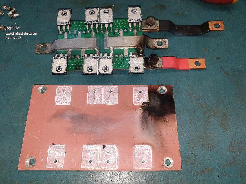
It's fortunate that the blowups haven't really caused any damage to the board and just needs a cleanup to look quite respectable again. The mosfet with the most damage had broken apart and from the molten globules I suspect one leg had flailed around arcing between the tx takeoff and the positive and negative rail ... until it went whizzing across the shed and hit the metalwork somewhere.
In cleaning up the thermal pad, I noticed a couple cuts in it and suspect it had arced through. I cleaned it all up and then cut away where the mosfets were going and fitted old style mica washers instead. In communicating with Tony, he suggested some 4.7k gate source resistors, in case there was an issue with losing drive or something ... so I fitted them to both bridges. Again it needed new optocouplers, so fitted them as well.
As you can imagine I was pretty apprehensive about firing it up again ... but eventually did last night. Then I came inside coz I couldn't face hearing any more explosions. I kept an eye on the wifi power monitor to see that it was still going ... and after an hour and a half at bedtime, I turned it back to the mains for the night.
Then back on again this morning ... and it's still behaving now.
I bought the themal pad from element14 and it wasn't cheap. When it arrived, it had been folded and not rolled and so the folds had damaged it and it almost seemed like it was coming apart. I cut those bits out, but I was disappointed in the quality. I've ordered some more that Solar Mike recommended and if I have any doubts, I'll go back to mica washers for all the rest.
Raggedy waveform with the second smallest inverter missing
Second blowup
Third blowup
Now with mica washers
Cheers, Roger
Murphy's friend Guru Joined: 04/10/2019 Location: AustraliaPosts: 592
Posted: 01:46pm 27 Mar 2024
Copy link to clipboard
Print this post
Hi Roger. That wave form above looks awfully familiar, saw that on my warpverter too .
And, strangely, when it blew it also was the smaller bridge causing me the most headaches. One cause was one of the 16 resistors on the control board going open.
Definitely go for the mica washers, I found the silicon rubber types wanting too.
I'm surprised you did not put those driver chips on sockets, sure makes it easier to swap them.
If you ever are having control board troubles, I have several of them and no longer any use for. Also, a fakeverter board which is useful to check the 4 drive wave forms without mosfets & transformers.
It's a great inverter (when it works) but I'm now convinced it's more suitable for a 96V battery bank.
nickskethisniks Guru Joined: 17/10/2017 Location: BelgiumPosts: 422
Posted: 02:34pm 27 Mar 2024
Copy link to clipboard
Print this post
Hi Roger, could you probe the source drain of the mosfets to see if you need snubbers? Or need 100V mosfets.
rogerdw Guru Joined: 22/10/2019 Location: AustraliaPosts: 809
Posted: 10:57pm 27 Mar 2024
Copy link to clipboard
Print this post
Yes, that waveform can't be good for everything, apart from the rattle it creates.
This one is the second smallest inverter for some reason. I have noticed that when one particular microwave is used the smallest two toroids protest the most.
Yeah, looks like the stuff I have is a lot more fragile than good old mica. The big advantage of course is the large areas you can cover with the new stuff.
Yeah, being an optimist can turn around and bite you sometimes. Having said that, there's lots of gear I've fixed over the years where the only long term fix is to remove the IC sockets that cause constant faults and solder the ICs direct.
Besides, I change smd's all day every day, so it's not exactly difficult ... and my bench is only 15 feet from the inverter ... so a couple minutes to unbolt the module, walk to the bench ... and turn on a couple of irons.
Thanks, I'll keep that in mind, though I do have a simulator board that allows me to see the same.
Yeah, I did agonise over whether to use IGBTs or mosfets ... and maybe I chose wrong. Am interested to see how Alston's goes with IGBTs and 48 volts. I guess I could backtrack and modify for IGBT's, but I'm hopeful it won't be needed.
As far as the 96V or higher supply, that's another option I wish I'd have understood better ... in fact I reckon I would have aimed for two forklift batteries in series and designed the rest from there.
The limiting factor now are my electrolytics ... they are only 63 volt ... so an equalisation charge on the battery can bring them close to 61-62 volts already ... so no room for increase there.
Having said all that, the machine has clocked up over 900kWh already and I have seen loads up to 8kW at times ... so it looks promising. And it has not been the larger two inverters which carry most of the load that have given me grief ... so I'm hoping it's just been a few unfortunate issues that have triggered the failures.
I've ordered a heap of new mosfets, but heavier HY5608W this time ... hopefully that will add some strength.
And it's been extremely helpful to have Tony on speed dial (well email anyway) for a bit of a reality check whenever I'm scratching my head or starting to panic because of problems. Cheers, Roger
rogerdw Guru Joined: 22/10/2019 Location: AustraliaPosts: 809
Posted: 11:04pm 27 Mar 2024
Copy link to clipboard
Print this post
Hi Nick, I have certainly checked waveforms and compared them between modules etc ... but I'm not really sure what I'm looking for.
I'm using HY4008W now and have ordered HY5608w for spares ... but are still both only 80V. Are there any 100V ones you would recommend?Cheers, Roger
Bryan1 Guru Joined: 22/02/2006 Location: AustraliaPosts: 1211
Posted: 02:17am 28 Mar 2024
Copy link to clipboard
Print this post
Rodger if you want some of those HY5608's mate I do have 25 of them here so come and grab em mate and you can give the same back when your order comes in. I won't be needing them for a while so if you do want them there here to get mate.
Cheers Bryan
rogerdw Guru Joined: 22/10/2019 Location: AustraliaPosts: 809
Posted: 02:46am 28 Mar 2024
Copy link to clipboard
Print this post
That's very kind of you Bryan. I have a heap coming about a week away, so if I get into strife in the mean time I will definitely take you up on your offer. That really takes the pressure off, thanks heaps.Cheers, Roger
nickskethisniks Guru Joined: 17/10/2017 Location: BelgiumPosts: 422
Posted: 08:45pm 28 Mar 2024
Copy link to clipboard
Print this post
I don't know, I want to see some serious spikes, ringing/oscillations going above 80V and perhaps reflected in the gate circuit.
I still use a lot irfp4110 mosfets in all of my builds
Ok, just some thinkering:
Seeing at your powerboard design, there is a short path between the mosfets and driver, that should be ok. Looking at the distance between your big caps and mosfets this could be improved to add some snubber caps. In my ozz inverter and mppt controller I'm using some PP capacitors 4,7uF 250V but really as close as possible.
Maybe something like this could be mounted on your bridge: (I'm not suggesting for using this exact part)
These can provide or store instant peak current for only a very little time. In theory big elco's are lacking this ability and are better suited for slow transients, just using some big bulk capacitors doesn't solve everything, there can still be short voltage spikes. I don't have expierence with the warpverter but I know its switching rather slowly, but the smaller H bridges are still switching a few kHz I think. But the transients can happen very quickly when using low gate resistors and perhaps maybe not realy neccesary. I you have really steep flanges you can expect some shoot true, leakage inductance of the transformers can induce voltage spikes over drain/source when the body diodes are not yet conducting. This energy is rectified by the body diodes and will flow back to the bulk capacitors. If I'm thinking about the warpinverter concept, there must be some energy that is constantly circulating no?
All reasons for me to make one someday
Murphy's friend Guru Joined: 04/10/2019 Location: AustraliaPosts: 592
Posted: 08:34am 29 Mar 2024
Copy link to clipboard
Print this post
Roger, thinking about your small bridge blow up (mine was the tiny bridge causing most grief), I somehow do not think that replacing 200A mosfets with 360A mosfets will fix that.
I'm sure you know about the power sharing of the 4 bridges: tiny bridge = 1/27th of total load small bridge = 3/27th of total load medium bridge = 9/27th of total load large bridge = 14/27th of total load
So, with your 8KW max load the small bridge takes 8000/27x3 = 889W. Not quite enough to blow 200A mosfets .
I too suspect its voltage spikes. You might want to monitor the gates of this bridge and see if the switching is clean, no excessive ringing and no shoot through.
I'm no expert with mosfet driving requirements but I did notice that fitting a ferrite bead to the drain leg cleaned up ringing remarkably well (on my EG8010 inverter).
Haxby Guru Joined: 07/07/2008 Location: AustraliaPosts: 419
Posted: 07:17am 07 Apr 2024
Copy link to clipboard
Print this post
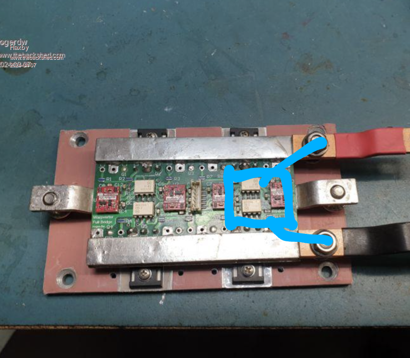
I also suspect voltage spikes. I'd suggest a beefy 100v or more 1uf metal film capacitor across each of the h-bridges. The electrolytics won't react as quickly as a metal film cap will. You might have some spare from the aerosharp inverters. Wire straight to the terminals like this:
rogerdw Guru Joined: 22/10/2019 Location: AustraliaPosts: 809
Posted: 01:40pm 14 Apr 2024
Copy link to clipboard
Print this post
Thanks Nick, sorry for the slow reply. We were away for a few days so I switched back to the grid while we were away in case I had any awkward calls from the kids while we were trying to have a break. Having said that, it's clocked up a lot more hours and has behaved itself so far ... so breathing a bit easier.
I will find some suitable caps to fit as you suggested, I can see the value of them to supress any spikes that might get through.
I've been very reluctant to poke around with the cro since it's been on the wall ... just a bit nervous. It was much easier while it was on its back on a trolley. I should have fitted some of those little curly links that you guys use when I had them on the bench last, to make it easier to plug my probes in to.
And yeah, it would be great to see another version of a Warpverter ... I'd love to see how you'd approach it. Cheers, Roger
rogerdw Guru Joined: 22/10/2019 Location: AustraliaPosts: 809
Posted: 02:03pm 14 Apr 2024
Copy link to clipboard
Print this post
All good points Klaus, thanks. It's funny what panic does to the thinking process ... well mine anyway.
I'm reminded of some 6A diodes I used to see that were a common fault on some boards I fix. They often came in shorted ... and because I couldn't find any close equivalent quickly, I fitted a 35A 400V bridge and used half of that. Then when I saw more, I just did the same thing because it had worked okay.
Then occasionally one would come back in with the 35A diodes shorted which made no sense when there were still many originals running with 6A diodes. Ater a while I thought I'd try a 1000V bridge ... and I've never seen one come back in since. It seems there must be some massive spikes on some of the supplies that was doing the damage. I also add a couple of varistors across the input lines too, so suspect that also helps.
Thanks for the reminder of the relative power levels too. The one that gave me the trouble was the second smallest at 3/27th of the total load ... so the fact that the larger two doing the bulk of the work have behaved themselves ... and are designed and laid out exactly the same, suggests it was more likely an issue with the actual module rather than a design flaw.
Having said that, an extra snubber type capacitor would certainly add another level of protection to all of them.
I am leaning towards the thermal insulator material having been the problem, so will change them all to mica eventually. The stuff came from element14 and was quite expensive, but they had just folded it instead of rolling it ... and it was clearly damaged by the folding process. Had started to disintegrate on the creases. I didn't use any of the damaged bits, but maybe the rest had deteriorated somewhat as well.Cheers, Roger
rogerdw Guru Joined: 22/10/2019 Location: AustraliaPosts: 809
Posted: 02:21pm 14 Apr 2024
Copy link to clipboard
Print this post
Thanks Phil, it certainly makes sense to add some and I'll have a look to find something suitable. If I can add eye lugs and fit them as you and Nick have suggested it should be relatively easy.
Just for an update for everyone, we had a nice sunny day today and the mppts were throttling back by lunch time already ... so I hooked up one of the underfloor heating circuits (3,000W) to make use of the free energy. Ran it for a bit over four hours and it was quite worthwhile.
We've been here 10 years and it had never been hooked up because the previous owners had only discovered they didn't have sufficient supply/wiring to cope with the load after they'd gone to the trouble and expense of fitting it under their new tiled floors. There are two seperate sections at 3,000 watts each.
It may be worth my while to add more panels and AC coupled inverters just to pour as much power into the underfloor heating to heatsoak the house when we have the chance.
I also switched on the air heater today for the start of its fourth season and it did a great job as well. It's the lead into and the lead out of winter that it is so effective ... not so much of course on really grey days.
Now that the Warpverter is up and running I've been working on the new 60 tube air heater again after a couple years of it just sitting there ... so I will add to that thread again soon.Cheers, Roger