
|
|
Forum Index : Electronics : Time for a new Warpinverter build - #3
| Author | Message | ||||
| rogerdw Guru Joined: 22/10/2019 Location: AustraliaPosts: 809 |
I've connected the earth wires between the MPPT's and inverter framework ... and hooked up the surge protectors in the combiner boxes. They will then be connected to the main earth inside the property meter box using the 3-core cable from the inverter. Sooo ... the moment of truth comes tomorrow morning. The electrician is coming to fit the ATS and hook it all up in the meter box. Yahoo!!!  Then I need to complete the covers for both devices and hide all my work.  Cheers, Roger |
||||
| rogerdw Guru Joined: 22/10/2019 Location: AustraliaPosts: 809 |
And it's all connected and running fine. 90+ amps coming in and house and workshop running off the Warpverter. Happy days. Still plenty to do ... make up some permament battery leads ... mount another 6kW of panels on the roof ... make covers for both units 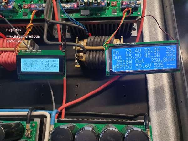 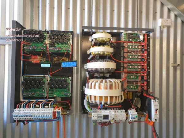 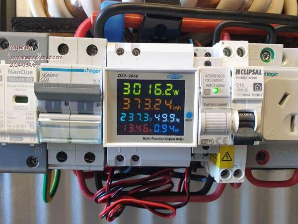 Cheers, Roger |
||||
| KeepIS Guru Joined: 13/10/2014 Location: AustraliaPosts: 1389 |
Brilliant work Roger, I love the effort that you put into winding those Toriods. The MPPT controllers came out really well. At first glance that construction could pass for an expensive commercial unit. Certainly says it means business.   It's all too hard. Mike. |
||||
| rogerdw Guru Joined: 22/10/2019 Location: AustraliaPosts: 809 |
Thanks for the kind words Mike, the toroids were very satisfying to build. Hard work and a lot of time ... but now I know the ropes, they don't phase me at all. I maybe should do some video of the winding process for those who haven't tried ... to show that it really isn't difficult at all ... and most everyone could replicate what I've done. I'm looking forward to having finished the covers for both units coz while they will cover all the works, it should make it look a so much tidier installation. Once I have the other half of the panels up ... on days like today I should be able to pump in 180 amps to my battery. At least in summer, that gives me more than enough. I'm also intrigued by your build of (the other) Mikes inverter version. Simplified and should be so much easier to build ... and with added reliability and strengths. I can see one in my future ... really need a backup of some sort. Not that mine is ever supposed to break down ... Cheers, Roger |
||||
| rogerdw Guru Joined: 22/10/2019 Location: AustraliaPosts: 809 |
The inverter has been going well and I've been using far more power than normal for the last few days ... roughly 35kWh each day for the last three days. That had depleted the battery somewhat by late evening so I've applied a charger for a few hours last night and a couple hours tonight ... to make sure it survives overnight. 174.8kWh over the last 5 days. We definitely need the additional 6kW of panels to be fitted and if it hadn't been so hot over the weekend I would have made a start. Three days of 41. Lovely. Autumn is here and we finally get some summer weather. Where did I read we were to have the hottest summer in 125,000 years. Pffftt!!! Certainly not here in SA ... been the least like summer weather I've seen in all my years. With the heat I noticed the transformers started to warm up a little ... about 47-48 degrees at one stage. Because I Haven't fitted the fan yet, I've had a pedestal fan aimed at it during the heat of the day. The heatsink remains pretty much at ambient which amazes me. The only other thing that gets hot are the chokes in the mppt controllers. Anyway, Alston's comments about fitting a Kilovac solenoid for emergency shutdowns etc got my attention ... so tomorrow I will shut it down for the first time since it was wired in on Wednesday and drill and tap a few holes to fit the solenoid and a current transformer for the DC-In line. The Kilovac is a 48-72v solenoid with a power economiser attached to the side. It pulls in strongly, then throttles back the current to 4mA to hold it in. One thing I did wonder about is that the main terminals have A1+ and an A1-. I don't imagine that current direction is important. There is also another N/O independant switch contact wires coming out as well. Not sure if I can use them for anything. The version I got was a IHV200HDANA Cheers, Roger |
||||
| Murphy's friend Guru Joined: 04/10/2019 Location: AustraliaPosts: 592 |
Perhaps not so important for 48V but you still might get an arc when they open while a high current is flowing. Give those arc extinguishing magnets (if it has them) something to do  . .Perhaps the instructions tell you how to connect it. |
||||
| KeepIS Guru Joined: 13/10/2014 Location: AustraliaPosts: 1389 |
Been using the Kilovac for a long time now, brilliant compact device for Inverter safety. In the event of a shorted FET, usually no inverter fire, cable damage or physical damage such as seen in the past, even with fuses and trip devices installed, and allows automated pre-charge as a bonus. Sounds like you have it running well even under those extreme conditions  It's all too hard. Mike. |
||||
| phil99 Guru Joined: 11/02/2018 Location: AustraliaPosts: 1805 |
If they have gone to the trouble of assigning a polarity it probably does matter. The datasheet doesn't give a reason but:- A) As suggested by Murphy's friend it might use permanent magnets to stretch and deflect the arc into a quench chute. If the current is reversed the arc will go the wrong way. B) Another possibility is the internal electronics requires that polarity. |
||||
| rogerdw Guru Joined: 22/10/2019 Location: AustraliaPosts: 809 |
Thanks Klaus, I've gone over the datasheet a heap of times but can't find any reference to it. Perhaps I'll dust it with some grinder dust and see if anything sticks. I noticed a ring of dust on the side of my DC cct breakers ... so they obviously have magnets of some sort. Thanks Mike, can you expand on how you're triggering the kilovac in the case of any of those faults ... and for auto pre-charge? Thanks Phil. Yeah the fact that they are clearly marked as different, yet the datasheet makes no comment got me questioning. I couldn't see or measure any connection between either of the large switch contacts and the control electronics wires ... or for that matter the extra set of N/O contacts. The pair of control wires first go to a small 20 x 30mm pcb attached to the side ... then disappear inside the coil. So I'm assuming my best option will be to have the battery side go into the A1+ terminal, short of getting a definitive answer. Thanks for the input. Cheers, Roger |
||||
| KeepIS Guru Joined: 13/10/2014 Location: AustraliaPosts: 1389 |
In Wiseguys controller, there is provision to switch a Kilovac, it's controlled by both the AC output status and obviously DC input status, I believe that this is also the case with the New Nano. This is how you get Precharge and power disconnect for any failure including current trip. In a pinch to get something quickly running, you could simply power it from a small modified 48v plug pack or DC-DC SMPS that can start at up at around 40V, allow for the Kilovac to draw around 1.5A (don't remember exactly) on pull in before the economizer kicks in. The leads on the side of the kilovac connect to the economizer board underneath the cover, two leads then run to the coil. FYI I always connect DC input from the batteries to terminal A1+. . Edited 2024-03-11 11:17 by KeepIS It's all too hard. Mike. |
||||
| rogerdw Guru Joined: 22/10/2019 Location: AustraliaPosts: 809 |
Thanks Mike, I've just rotated it 180 degrees to accommodate those connections. Bit trickier with solid bar connections than with cable. I'll initially drive it from the battery input ... but looks like I'll need to do some similar programming to control startup and shutdown along with as many fault conditions as I can work out. I'm even starting to warm to Alston's idea of a overtemp or even fire alarm shutdown. No pun intended. When I turned the inverter AC-out off this morning I took a risk and left everything on in the house. The ATS changed over quickly enough that the PC's all stayed on and all I noticed was a flicker to the fluros in the shed. No one has commented so far at home here. This is the ATS I have here ... the 100 amp version. The 125 amp one was not listed when I first bought mine. When the electrician tested it when he installed everything I was amazed at how quickly it changed over each way ... so thought it was worth the risk ... plus the power goes off and on once in a blue moon and I have no control over that. Edited 2024-03-11 12:27 by rogerdw Cheers, Roger |
||||
| KeepIS Guru Joined: 13/10/2014 Location: AustraliaPosts: 1389 |
Would you believe that I have two 3 pole units like those  I forgot to include over temp when I answered, basically any condition that stops SPWM output will shut it down, so over temp included. I love the smoke alarm idea, I have modules here ready to fit. Just an extra layer of safety, especially when unattended in 40°++ heat. From memory when Alston's first posted that, I said to Wiseguy, why the hell didn't we think of that. Yes some lights give a flicker, mainly my LED fluros. Who cares It's all too hard. Mike. |
||||
| rogerdw Guru Joined: 22/10/2019 Location: AustraliaPosts: 809 |
Where does the current trip signal come from with yours ... is it from the controller itself ... or an actual trip level from your current meter? Thanks. Cheers, Roger |
||||
| KeepIS Guru Joined: 13/10/2014 Location: AustraliaPosts: 1389 |
In the my running controller, the signal comes from a 400A Hall Sensor, it's shown in my last Inverter build. That drives a Peak input current Analogue Meter, and feeds the Controller Current trip circuit, which in turn (among other controller signals) trips the Kilovac DC input isolation solenoid. In Wiseguys new Nano controller, the board has an Extension current trip input for that, and any other trip devices you may like to use, like a smoke sensor trip, but these need a little bit of external circuity for the devices. So obviously, you need a Hall effect sensor in both cases. . Edited 2024-03-17 14:08 by KeepIS It's all too hard. Mike. |
||||
| rogerdw Guru Joined: 22/10/2019 Location: AustraliaPosts: 809 |
Thanks Mike, I had read that back when you were building your first one and even bought a couple of the current transformers at the time ... but I had forgotten they were also called Hall Effect sensors ... so in the interim, was thinking maybe you had changed to something else. I'm catching up slowly. At the time Klaus asked a question as to what the meter shows when there's a steady current flowing through ... say 100 amps ... and I have the same question. I couldn't see a definitive answer in your follow up. I'm trying to work out what indicators I need on my machine ... peak current or steady state current etc. It's wonderful having it all working, now I just need a bit more feedback for better management. Cheers, Roger |
||||
| KeepIS Guru Joined: 13/10/2014 Location: AustraliaPosts: 1389 |
All Input calculations and the normal display of current is NOT Peak current. The Peak Indicator is brilliant when looking for Loads that might Trip the inverter over current logic, or more importantly, might damage the inverter. These Peaks are usually very fast transient pulses from things like Switch mode power supplies (SMPS) power on, they are in everything, and big induction motor start current. No matter how transient the current pulse is, the FET Power stage has to handle that transient input pulse Current. A typical small plug pack for a LED monitor will normally peak at around 150A DC into the inverter at power on, however once every month or so it will trip the inverter OC, the current needed to trip mine is 550A, the peak display was over that on that small SMPS AND many other SMPS devices. Once in a blue moon these things cause very high current pulse when starting. Because of these levels, I have DC input current trip implemented as well as AC current trip. So it Will trip on them. Funnily, a typical smaller inverter may not trip, but over time, like 6 months from now, you throw a switch or turn the inverter on -- and bang. As you know there has been a lot of work gone into finding the cause of random inverter blow ups, these current spikes do not help and could cause accumulative damage over time. This problem is also consistent across various bigger Bench SM power supplies, every so often there is an out of the blue spike in input current. You will never see this with a typical clamp meter or inline current meter. This is compounded when you switch the House running load from Mains to the Inverter. If you are off grid and never switch to mains, then that part is not a problem. But it is a problem with off grid when powering up the inverter and then switching the off grid load onto the inverter, if you know what loads could cause a problem, they can be removed before switching to the Inverter. I've finally decided to make some small auto "slower start" modules for various SMP supplies and other Toriodal test gear. Very simple to do and that's my nest project after finishing the smaller backup inverter. Hopefully I can forget about them then. I have left out a lot of testing detail, and this is just a simplified answer. EDIT: To answer the question on the averaged DC 100A input ,some have a lot of smoothing to show this current without the display jumping around. It depends on the load and the fast DC input current pulses that load is causing, but the Peak can be anywhere from around 1.5 to over 2 times that averaged smoothed input. It's not a nice smooth DC input signal on the inverter, put a DSO on the DC line at high current inputs and you might be surprised. . Edited 2024-03-19 15:14 by KeepIS It's all too hard. Mike. |
||||
| rogerdw Guru Joined: 22/10/2019 Location: AustraliaPosts: 809 |
Thanks Mike, that is all very helpful. So I am assuming that your inverter occasionally trips out with some of these rogue loads ... and that your ATS just swaps you back to the mains until you reset the inverter? I can certainly see the value in being able to identify loads that might overload or blow crap up and either get rid of them or somehow alleviate them. I had no idea small plug pack supplies like you mentioned were that big a risk ... I kept thinking all your big equipment and things like big air compressors or air conditioners etc. I'm yet to try our monster aircon or even my big saw bench. Not quite game enough yet. I'm hoping that we can remain offgrid, but there will be times I have to switch off the inverter and drop back to the grid ... but of course then when we swap back there is potential for problems. It will be interesting to see how your soft start or slower start ideas work out, good luck with them. In the meantime I will continue making plans to fit my hall effect current sensor on the input. I probably should have done that before I fired it up, but it's behaved itself so far ... though I do want to be able to identify potential troublemakers and learn how everything plays together. Is it okay if I copy your circuit to try and replicate what you've done please. Would certainly save me a lot of headaches. Thanks. Cheers, Roger |
||||
| Murphy's friend Guru Joined: 04/10/2019 Location: AustraliaPosts: 592 |
I have done just that Roger, that peak detector works very well. I should have a spare PCB if you want one. I think Mike's was on vero board. |
||||
| KeepIS Guru Joined: 13/10/2014 Location: AustraliaPosts: 1389 |
 Rodger, I used an old analogue meter to show the peak current just because it looked neat, well to me at least, and it's easy to see the pointer from across the room. The slow start I want for these various plug packs is not really that slow, just enough ramp to stop random high inrush current spikes. The Aircon, Microwave, Bench saws and Drop saws are all non events. Like you said the Big Compressor, Dust extractor and 2m high Bandsaw are the normal big inrush loads, but are still way below some small Plug pack spikes, again randomly, and the Variac. That Variac (big toriod) is an inverter death spike every 1 in 5 turn on, and can easily trip the Mains as well, again not every time, I have two of them and they are renowned for doing this. I often see the Input Meter pin against the pointer stop at 600A  It's all too hard. Mike. |
||||
| phil99 Guru Joined: 11/02/2018 Location: AustraliaPosts: 1805 |
A few decades ago the EU introduced regulations that required electronic devices to minimise the effects on the mains of the large capacitors in them. Compaq and HP simply added an iron cored choke to the input. This raised the PF and limited the inrush current. Later versions used a switch-mode pre-regulator between the rectifier and the main storage capacitor. A cheaper method is an NTC thermistor in series with the mains. It has a cold resistance of a few tens to hundreds of ohms dropping to a few ohms when heated by the normal current of the device. Another option for capacitive loads is a triac with a zero-crossing trigger circuit. The Variac has the opposite problem, core saturation if you happen to switch on close to a zero-crossing. Inrush will be minimal if it is switched on close to peak voltage. |
||||
