|

|
Forum Index : Microcontroller and PC projects : Standardization Please .. ?
| Author | Message | ||||
| thwill Guru Joined: 16/09/2019 Location: United KingdomPosts: 4036 |
Not yet. I want to throw v0.7 over the fence and put out any resulting fires first. However it is at the top of the list for v0.8+:  Incidentally when I speculated a couple of months back during one of your "quiet" periods, I thought this might be what you were working on ... I guess I was wrong  . If you do get bored waiting for me and start tackling it yourself I'd appreciate a heads-up to avoid duplication of effort. . If you do get bored waiting for me and start tackling it yourself I'd appreciate a heads-up to avoid duplication of effort.Best wishes, Tom Edited 2024-09-14 23:58 by thwill Game*Mite, CMM2 Welcome Tape, Creaky old text adventures |
||||
| Mixtel90 Guru Joined: 05/10/2019 Location: United KingdomPosts: 6779 |
These controllers are still odd. I have two and they are both giving the same result. Bits 6 and 9 (counting from 1) are both stuck high (instead of 00 I'm seeing &h0120) and the direction pad isn't reading anything at all. If I subtract %h0120 from the value returned by gamepad then everything else makes sense. I'm not using interrupts, just "bits = device(gamepad gpchan, b) They *look* like the generic USB controllers and, obviously, they are partially working. I've just used an on-line controller tester and everything is sending something so the controllers aren't faulty in that respect. The direction pad seems to be giving the same signals as the lower left stick on a XBOX 360 controller or the left stick (not the pad) on a generic XBOX/Switch controller. . Edited 2024-09-15 01:10 by Mixtel90 Mick Zilog Inside! nascom.info for Nascom & Gemini Preliminary MMBasic docs & my PCB designs |
||||
| thwill Guru Joined: 16/09/2019 Location: United KingdomPosts: 4036 |
What does MM.INFO(USB id) return ? Presumably some different value that the firmware can hopefully accommodate. Tom Game*Mite, CMM2 Welcome Tape, Creaky old text adventures |
||||
| Mixtel90 Guru Joined: 05/10/2019 Location: United KingdomPosts: 6779 |
mm.info(usb id) = 4 as it's on channel 1 mm.info(usb 1) = 130 if that means anything. :) These seem to be emulating an analogue stick pushed to the limits in each direction, not switches, so they don't appear as bits. . Edited 2024-09-15 01:53 by Mixtel90 Mick Zilog Inside! nascom.info for Nascom & Gemini Preliminary MMBasic docs & my PCB designs |
||||
| Volhout Guru Joined: 05/03/2018 Location: NetherlandsPosts: 4222 |
@Peter, I looked at the schematics of your new board and have following comments - As Mick: how to upgrade firmware (electrical disconnect USB hub) - How to upgrade firmware: when you connect TP2/3 by laying pico2 flat on the surface of the board, you cannot plug the micro USB plug in (you need to elevate the pico from the board) unless you place the pico at the board edge. - When you connect TP2 and TP3, you can also connect TP4. This is the pin that switches the PSU into PWM mode. But you bypass the PSU by a linear regulator. The pin is useless. This useless pin can be used as a software controlled RESET for the USB hub chip. Might come in handy if for some reason the USB hub chip is malfunctioning -or- but this must be tested... to allow firmware updates without disconnecting the USB chip, since software can keep it into reset. For that it would need a pullup resistor to that pin that overrules the 100k pull-down on the pico2. So a 4.7k or so). - Maybe add 2 capacitors at the USB hub crystal. So in case theoscillator is not running well, you can add som 10pf caps. This will of coarse also work on a board that uses the on board PSU. That PSU will (as a side effect) change operating mode. But that will only impact efficiency and ripple, but not operation. Both states of TP4 there will be 3.3V. Actually, when the envisioned 315MHz is used, the PSU will normally operate in PWM mode anyway since this is the operating mode selected when running higher power, regardless TP4 state. But the software function in MMBasic to switch the PSU mode must be bypassed. I like the GP0..GP7 free, but can also imagine need for a ADC input. This is all up to you to decide. Since SPI is only used for the (software bit-banged) SD card, it may be possible to (in line with earlier 2040 VGA platforms) to leave GP0..5 free, and keep access to 2 of 3 ADC's (GP26/27 would be nice since some commands use GP26 as starting ADC channel). If you complete the design, I will definitely order a build of 5 for mainland Europe. Will keep 2 myself, and will have 3 available for peoples that would like one (Germany has low shipping cost from Netherlands). Volhout Edited 2024-09-15 02:34 by Volhout PicomiteVGA PETSCII ROBOTS |
||||
| al18 Senior Member Joined: 06/07/2019 Location: United StatesPosts: 205 |
Peter’s new design looks great. One small design request - switch to a different reset button design. I recently bought a board for retro computing with the 90 degree momentary contact button and I broke it within 2 hours of unboxing. I was able to make the board functional again by soldering a standard momentary button board flat, on top of double-sided foam tape. My point is there is the type of button you selected has little mechanical strength. |
||||
vegipete Guru Joined: 29/01/2013 Location: CanadaPosts: 1109 |
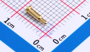
With Peter's new design, I presume surface mount soldering the PICO2 is needed to allow the TPs (for USB) to soldered too. To allow headers instead, have a look at pogo pins. Consider JLCPCB part numbers C5221293, C5221284 and C5221294 (as examples.) It might take some experimenting to get the length right, but these pogo pins would press up against the TPs when the PICO2 is plugged into headers, removing the need for direct soldering. I have a microcontroller module in my collection that uses this method quite effectively.  Visit Vegipete's *Mite Library for cool programs. |
||||
| al18 Senior Member Joined: 06/07/2019 Location: United StatesPosts: 205 |
I prefer soldering the Pico2 with a pin header and thru holes. This is due for rework and testing purposes. I previously built 3 PicoVGA by hand and 3 colors were slightly off on one board. I admit I’ve never tried to desolder a surface mounted Pico with solder wick and a manual solder pump - is it possible? |
||||
| Mixtel90 Guru Joined: 05/10/2019 Location: United KingdomPosts: 6779 |
I'd tape it over with tinfoil and kapton tape then use a hot air gun. As I have a solenoid operated solder sucker I might take the worst off with that first. You need proper heat on any GND connections as they quickly conduct it away. The point of surface mounting it is because it's cheaper to do that. JLCPCB don't charge a lot to surface mount but soldering 40 through-hole pins is expensive as it has to be hand done. Mick Zilog Inside! nascom.info for Nascom & Gemini Preliminary MMBasic docs & my PCB designs |
||||
| Volhout Guru Joined: 05/03/2018 Location: NetherlandsPosts: 4222 |
Oh Peter Maybe change the hdmi resistors from 270 to 220. Some experience problems with the signal levels. The ACTIVE led is wrong polarity. Volhout Edited 2024-09-15 04:57 by Volhout PicomiteVGA PETSCII ROBOTS |
||||
| al18 Senior Member Joined: 06/07/2019 Location: United StatesPosts: 205 |
The PicoH has soldered header pins and sell for $1.00 more than a Pico. The PCB assembler would install the 20 pin header and the PicoH into the board and both would be soldered by a wave solder machine. No manual soldering. |
||||
| matherp Guru Joined: 11/12/2012 Location: United KingdomPosts: 9106 |
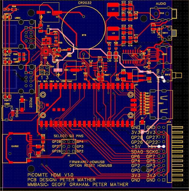
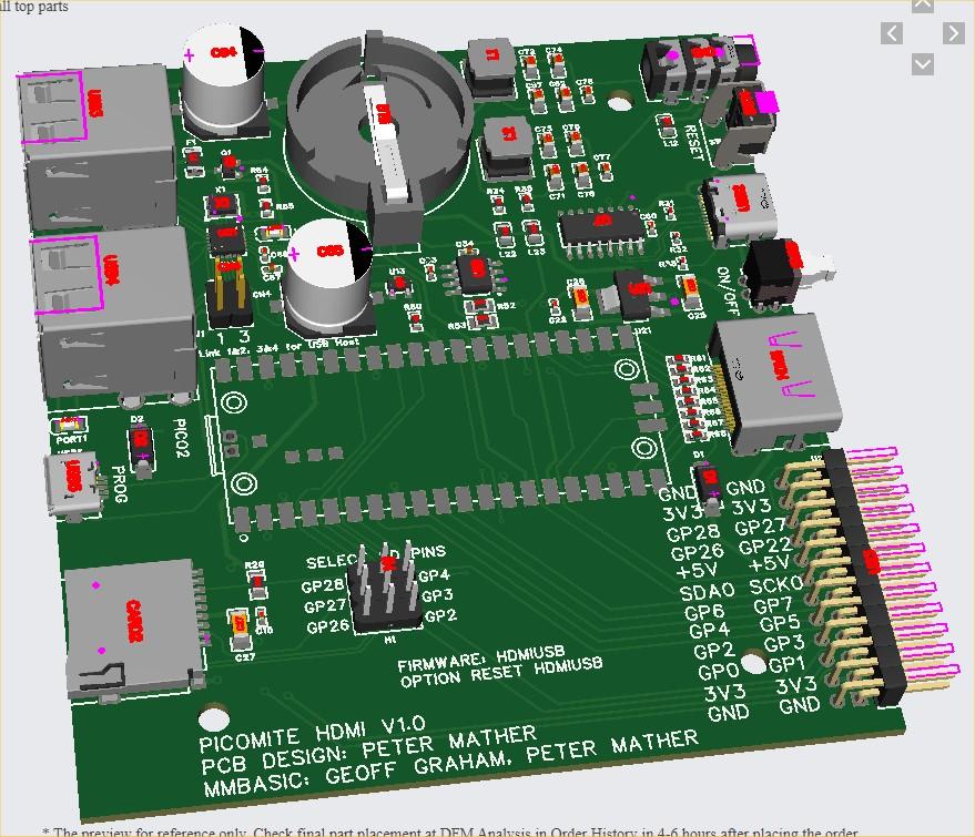
Here is the next (last?) iteration. Jumper to isolate hub. Pins GP22, GP26, GP27, GP28 added to external header and jumper to select which SPI pins to use for SD. Board edge USB connector for programming Schematic 93045abd-a2e3-4e9d-8545-9e7e6924be13.pdf   |
||||
| robert.rozee Guru Joined: 31/12/2012 Location: New ZealandPosts: 2350 |
hi Peter, is there any chance of adding 40x holes so that a socket can be installed for the pico2 module to enable it to be fitted later and/or replaceable? cheers, rob :-) |
||||
| matherp Guru Joined: 11/12/2012 Location: United KingdomPosts: 9106 |
Can't work with it socketed as it needs to connect to TP2 and TP3 on the bottom |
||||
| javavi Senior Member Joined: 01/10/2023 Location: UkrainePosts: 207 |
Is it possible to move the Pico2 module closer to the front edge of the board, so as not to make an extra USB connector for flashing the Pico2? By the way, you can combine the HDMI landing site with the VGA, or place it next to the HDMI and get a universal PicoMite HDMI/VGA board. In this case, the expansion port should be placed on the side!? Parallel connection of these two video outputs with their resistances to Pico does not interfere with each other in operation, this has already been verified on other projects and there is even the possibility of auto detection of which interface is currently connected. Edited 2024-09-15 22:02 by javavi |
||||
| robert.rozee Guru Joined: 31/12/2012 Location: New ZealandPosts: 2350 |
i can work around the connection to DP and DM easily enough. cheers, rob :-) |
||||
| matherp Guru Joined: 11/12/2012 Location: United KingdomPosts: 9106 |
I could but given the DVI signals are running at up to 382MHz with data sampled on both clock edges I wanted to keep them as short as possible. I'm going to get a couple made as currently designed, first thing is to prove the hub circuitry is correct. If all OK I'll look at possible other changes before I release the gerbers. It is important all the connectors are on the long sides so the design fits nicely in the case. |
||||
| Mixtel90 Guru Joined: 05/10/2019 Location: United KingdomPosts: 6779 |
And you have to avoid those pesky fixing holes! :( Incidentally, my original designs used the PCB depth that Hammond gave for the case. After having one made I realized that because of the plate thicknesses the board actually needed to be closer to them. The boxes I got, with Hammond labels, will easily take boards that are 2mm deeper. That makes life easier for things like micro SD sockets. I'll know more about this in a couple of weeks when my Gamma boards arrive. :) Edited 2024-09-15 23:11 by Mixtel90 Mick Zilog Inside! nascom.info for Nascom & Gemini Preliminary MMBasic docs & my PCB designs |
||||
| Volhout Guru Joined: 05/03/2018 Location: NetherlandsPosts: 4222 |
@Peter, I assume you are aware that by surface mounting the pico2, a pico2-plus will not work on this board (components on both sides). I tested the PSRAM as implemented on the pico2-plus, and it is around 10x slower than the normal RAM. This simple test running 6.0.0 beta 5 with PSRAM enabled. The array=80kbytes, and fits into RAM dim a(10000) timer=0 math set 13,a() print timer This takes 1.5ms (CPUSPEED 252MHz) When I increase the array size to 800k, no way it can fit in RAM, so PSRAM must be used. dim a(100000) timer=0 math set 13,a() print timer This takes 183ms. This is more than 100x more time, for a 10x larger memory block. This means that PSRAM is definitely a lot (10x) slower. It may even get worse when you would do random updates to the PSRAM, since you run out of cache more often. Volhout Edited 2024-09-17 05:57 by Volhout PicomiteVGA PETSCII ROBOTS |
||||
| matherp Guru Joined: 11/12/2012 Location: United KingdomPosts: 9106 |
I'm not recommending the Pimoroni boards for any MMbasic uses. They won't overclock like the Pico2 and as you indicate the Plus is not physically compatible (and is expensive). When chips become available I will develop my own boards like I have for the RP2040. |
||||