Notice. New forum software under development. It's going to miss a few functions and look a bit ugly for a while, but I'm working on it full time now as the old forum was too unstable. Couple days, all good. If you notice any issues, please contact me.
wiseguy Guru Joined: 21/06/2018 Location: AustraliaPosts: 995
Posted: 12:16pm 13 Apr 2024
Copy link to clipboard
Print this post
Not familiar at all - way too neat, they look like commercial units.
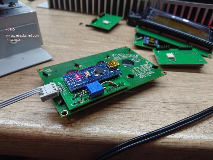
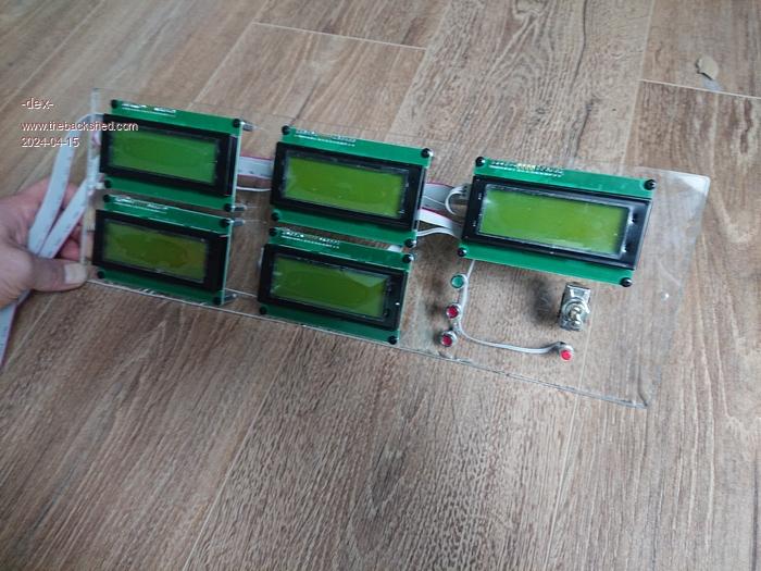
Good job Mat, a very high quality build, you must be pleased with the results too.
When is the big MPPT test - how many strings of Panels do you have at present ?If at first you dont succeed, I suggest you avoid sky diving.... Cheers Mike
Thanks. MPPTs hasn't been tested yet. Let's hope it doesn't turn out to be expensive commercial fireworks
Now I have 3 strings in a 3s2p arrangement. Open circuit voltage ~110V, at maximum power (2.5kW) the voltage drops to approximately 90V - this is what the datasheet says, but it will be verified soon.
So far, for testing purposes, I have used a set of 4 small AGM batteries as a power source. The inverter has been pre-started, so there is no chance of any wiring errors.
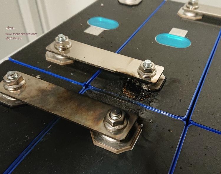
Today I installed the target set: 16pcs of lf280k cells. The links were pressed together using two sheets of metal and screws. The voltage of the entire battery pack was 53V. Everything looked OK.
I switch onthe MCCB breaker that supplies voltage to the busbars to the system and at that moment there was a huge flash, a beam of sparks from the cell, I realized that it was a short circuit and immediately disconnected the fuse.
How did this happen? I don't know. But I found out how dangerous these small, inconspicuous blue boxes are.
After this accident, I checked whether the "+" and "-" buss were shorted behind the switch. After MCCB breaker there is no short circuit.
I can only add that the negative busbar is connected to ground, and the entire housing is also connected to the ground busbar. In other words, the entire case has a "-" battery potential
Is it possible that the short-circuit current flowed through the cell housing into the system housing? I didn't use any additional spacers/separators.
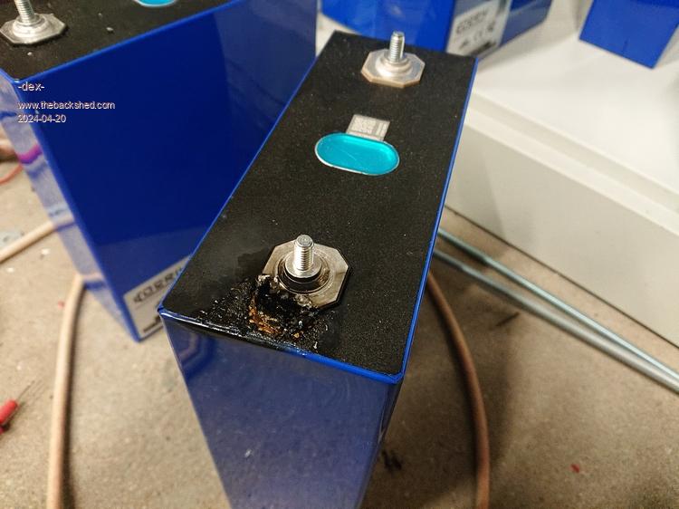
I dismounted battery pack and it turned out that some of the cells were slightly injured and could have come into contact with the metal screw, and then screw with metal housing.
I further checked whether the cell's aluminum casing had any potential under the blue foil. It turns out yes. Some of them have "-" on the housing, and the rest have "+" on the housing. However, it is not a full connection with the terminals, there is some resistance between them.
rogerdw Guru Joined: 22/10/2019 Location: AustraliaPosts: 796
Posted: 12:47pm 20 Apr 2024
Copy link to clipboard
Print this post
Ouch, that would have given a fright. Sorry I have no experience with those cells at all. I have read of some types where there is concern about the insulation on the outer battery case being too thin or being damaged and causing issues.
It's always nervewracking switching things on the next time after a blowup ... well it is for me anyway ... so good luck when you fire it up again.
Your mppt chargers turned out really well too, congratulations. I plan to fit my displays and some analogue meters like that to the front cover ... when I get to that stage.Cheers, Roger
Murphy's friend Guru Joined: 04/10/2019 Location: AustraliaPosts: 583
Posted: 01:06pm 20 Apr 2024
Copy link to clipboard
Print this post
I do not think it is a good idea to ground the battery negative to chassis. I certainly do NOT do that in my inverters.
Instead I connect the AC ground to the chassis/housing.
That way there is no bang if one of your battery leads accidentally touches the housing cabinet.
analog8484 Regular Member Joined: 11/11/2021 Location: United StatesPosts: 89
Posted: 07:06pm 20 Apr 2024
Copy link to clipboard
Print this post
Any large lithium battery can cause havoc quickly due to the much lower internal resistance compared to lead-acid/AGM batteries. I also learned the hard way. I second Murphy's suggestion.
KeepIS Guru Joined: 13/10/2014 Location: AustraliaPosts: 1358
Posted: 09:35pm 20 Apr 2024
Copy link to clipboard
Print this post
The aluminum case is normally at one potential- some brands cells normally come with a type of fiberglass spacer sheet, can be bought in packs if you have nothing suitable, these protect close mounted cells, a 54v LifePO4 battery bank is seriously extremely dangerous.
That looks like a breakdown between the case and the opposite polarity terminal. That should not happen. Shorting out a 54v bank normally vaporizes the object causing the short or cable. Did you have a BMS connected - that's one of the things it's meant to stop- total battery destruction with almost unlimited current available in the event of a external short.It's all too hard. Mike.
Solar Mike Guru Joined: 08/02/2015 Location: New ZealandPosts: 1123
Posted: 10:08pm 20 Apr 2024
Copy link to clipboard
Print this post
That would give you a fright! With these type of battery cells the blue shrink wrap insulation is not sufficient to prevent cases shorting; always place an insulator like thin glass fibre sheet or thin polycarbonate sheet between all mating cell housings and the bottom if sitting in a metal box.
That splat looks like between the case and terminal, wow something wrong possibly in that cell or the case was touching another.
phil99 Guru Joined: 11/02/2018 Location: AustraliaPosts: 1783
Posted: 08:36am 21 Apr 2024
Copy link to clipboard
Print this post
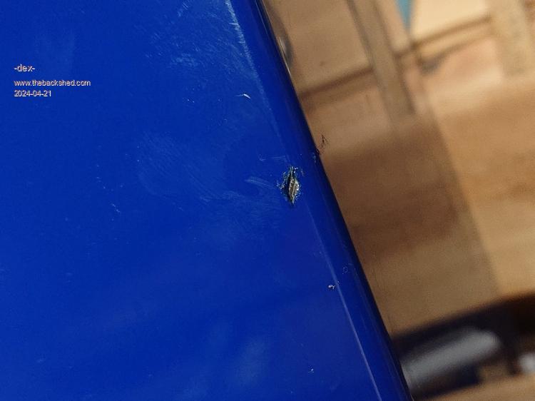
If the base of that cell was in contact with the metal shelf then the connection between the terminal and the case would blow like a fuse. Check the base of that cell for damage to the blue skin.
If that is what happened it is possible that cell can still be used if the cells sit on plastic.
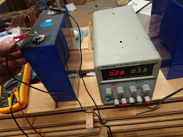
Yes, the blue insulation is damaged. This is a small damage and there is no trace of high current flow, nor is there any trace on the screw. If there was a knocking surface, it was not large considering the current that flowed.
I'm not sure if I want to continue using it. This short circuit didn't make much of an impression on cell - the voltage dropped by less than 100mV. However, there is a hole from which some liquid leaked.