
|
|
Forum Index : Electronics : Builiding of a complete 6kW PV inverter with MPPT chargers
| Page 1 of 9 |
|||||
| Author | Message | ||||
| -dex- Senior Member Joined: 11/01/2024 Location: PolandPosts: 104 |
I'm starting a new topic about building a complete solar inverter in which I would like to share the results of my work, and, more appropriately, an account of the construction of a home power system. As a new member of this forum, at the outset I would like to say hello - I am Mateusz, or simply Mat. In my country I have no one to discuss with about building an inverter, I came across this forum which is a mine of knowledge about building inverters for home brewing. I went through many topics on this forum. In the meantime, I purchased the OzInverter Book from Leslie R A Bryan albeit the initial admiration for this project passed and I started working on my own circuit. In the meantime, I came across the wiseguy inverter project and it basically meets all my expectations both in terms of power and layout solutions. Why reinvent the wheel? The boards for the inverter are already with me. I would like to say a big thank you to user wiseguy who helped me a lot and probably if it wasn't for his support I wouldn't have started this project. The project is to include the construction of an inverter with a continuous power min. of 6kW and a peak of more than 10kW, and the construction of MPPT chargers according to the poida design (150V 45A design) 3-4 pieces. The system is to work 24/7 and is to be the first source of electricity at home. When the sun goes out and the current in the battery runs out the automatic switch (ATS) will switch to the grid. The big challenge is to get a steel core for a toroidal transformer. I looked through everything I have at my place and found the core, it came from disassembly, I have two identical ones. 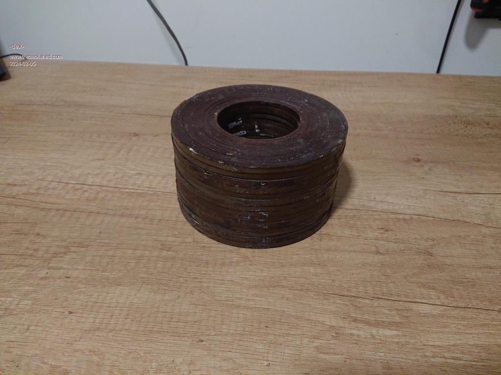 Perhaps power-wise by gluing two together I would achieve the required power, but after calculating the windings it comes out that they will not fit in the window (OD=145mm, ID=65mm, H=80m, 7kg weight) Basically it is 14 small disks glued together. I will save it for later. I asked a lot of companies making transformers or cores and no one wanted to talk to me, I'm just too small - this was no surprise to me. But finally one company spoke up and made an offer to inquire. OD=250mm, ID= 160mm, H=100mm, weight 21kg. Chamfered edges, annealed steel, made of material in grade M095-23P/ETH095-23. that's it! 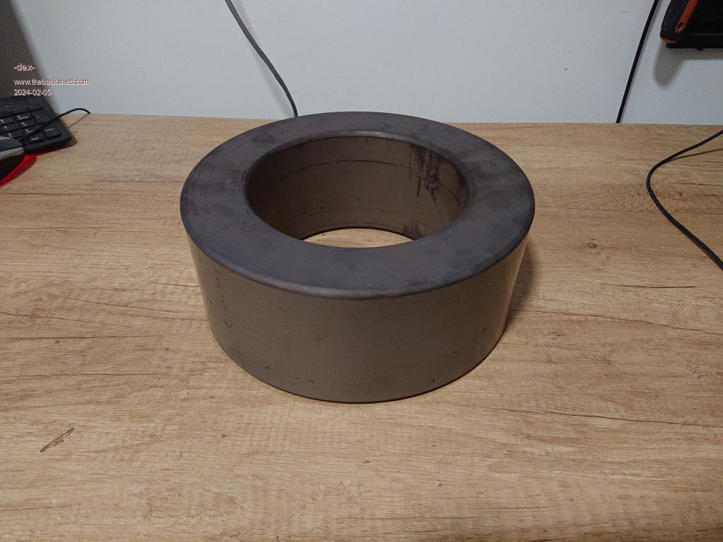 With CD for size refernece 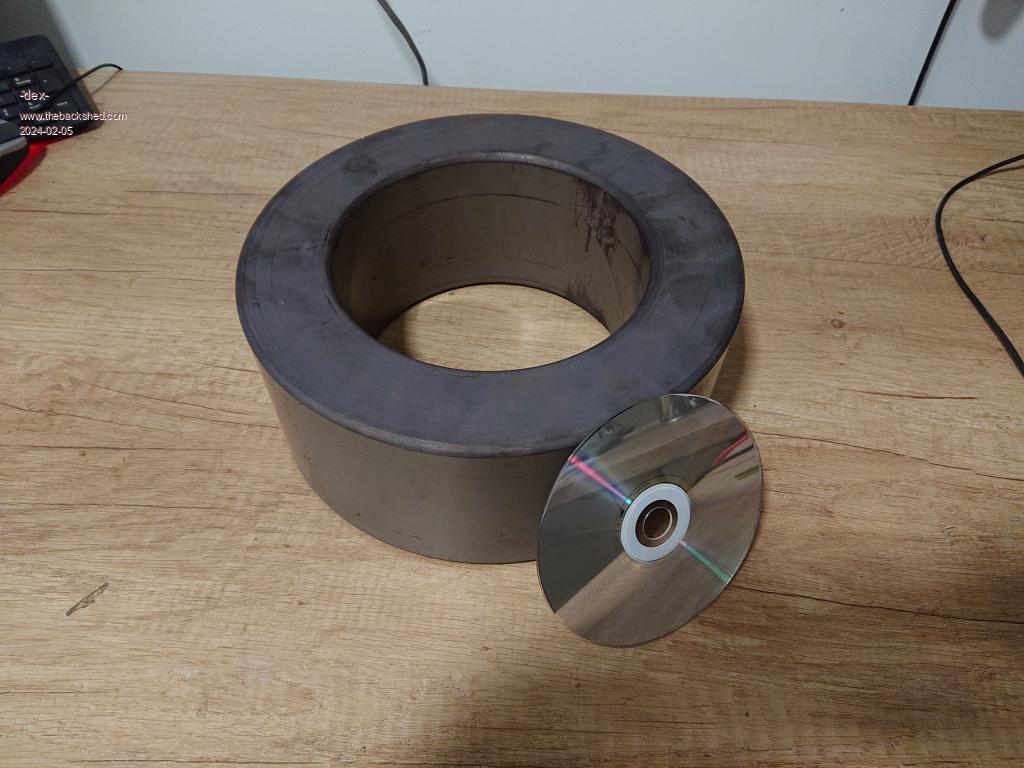 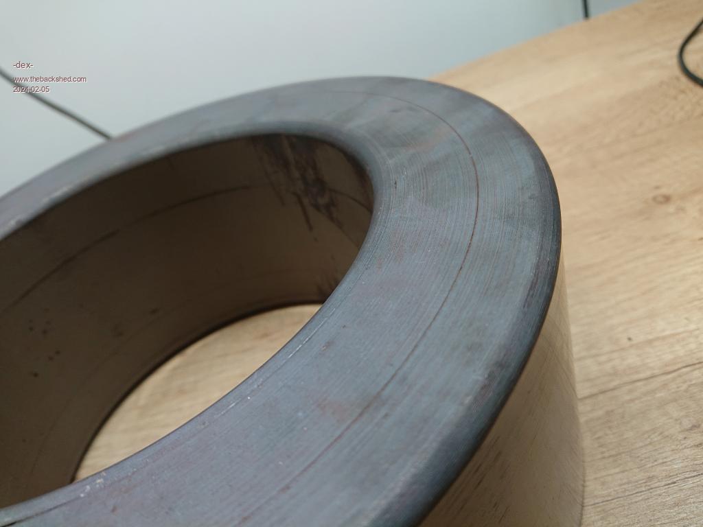 And for compare sizes two of them 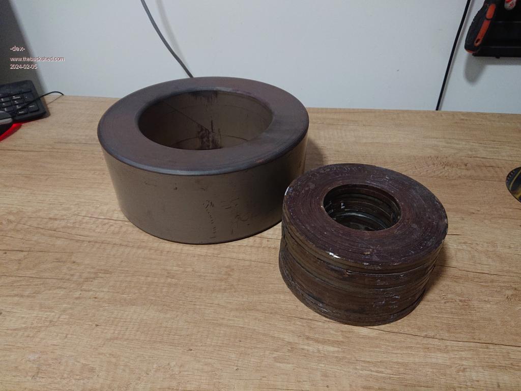 I assume that I would like to get a flux density of 1.4T. I think this is a compromise between maximum efficiency and idle current. I also assume that I will use 1.8mm wire and 4 layers for the winding. Will this be correct? This is a solution taken from the OzInverter book, I have access to wires of a different diameter. I encourage you to participate in the topic and would appreciate any help and answers! |
||||
| Solar Mike Guru Joined: 08/02/2015 Location: New ZealandPosts: 1214 |
The higher your flux density, higher standby loss in the core; a lower flux density of 1 Tesla (10,000 Gauss) has been suggested by others here as a optimum value to keep core losses to a minimum. To calculate the turns required for your core This Calculator allows you to input the core cross section area in cm^2, mains frequency and number of turns. play with the turns value to get the required flux value. For copper wire size, aim for 4 amps per 1mm^2 area; then you can see if that size wire will fit on the core, compromises may have to be made to get everything to fit. Cheers Mike |
||||
| wiseguy Guru Joined: 21/06/2018 Location: AustraliaPosts: 1296 |
As I haven't actually wound a toroidal transformer yet I decided to use the calculator to get a feel for the process. For 240V and 240T and 50Hz it computed 0.01 Gauss - then I noticed frequency input was in megahertz not hertz - dummy! The answer then became 10,010 gauss but I do encourage others with real toroidal experience to lead Mateusz to the correct solution. It is a good calculator but it would be more user friendly if it accepted input in hertz instead of megahertz which for 99.99% of users I think would be the actual case? Edited 2024-02-05 08:45 by wiseguy If at first you dont succeed, I suggest you avoid sky diving.... Cheers Mike |
||||
| Murphy's friend Guru Joined: 04/10/2019 Location: AustraliaPosts: 678 |
Hi Mat, I too would suggest you stick to 1 Tesla flux density. Your core cross section, at 45 sq cm, is a bit small but will do. For example, my 6KW inverter uses a toroid with 63.9 cm sq cross section. Assuming you have 220V 50Hz mains power in Poland then, for your core, you need to wind 220 turns for your secondary and 24 turns for your primary. You certainly have plenty of hole space to get your windings through. My core has a 100mm hole but with less turns required for 1 Tesla (160t secondary./ 18t primary.) I managed to fit all with a little space left. Have fun winding, its heavy work with that core but there is plenty of advice on this forum how to go about it. |
||||
| -dex- Senior Member Joined: 11/01/2024 Location: PolandPosts: 104 |
We have here 230V 50Hz as standard. I have checked these values in other calculator and looks like below. It takes into account the current density proposed by Solar Mike at 4A/mm2. The initial value suggested by the calc is 2.4A/mm2. Decreasing this value lowers the available power score. Edited 2024-02-05 20:29 by -dex- |
||||
| Murphy's friend Guru Joined: 04/10/2019 Location: AustraliaPosts: 678 |
We use a 9:1 secondary to primary turns ratio for a nominal 48V battery bank. All my EG8010 & nano inverters, except the first one (power jack), use that 9:1 ratio - it works. A tip: when calculating how many turns of wire fit on one layer in the toroid hole the calculated number is not archivable by hand winding. Aim for 10% less turns per layer than the calculated number. Unless you have a gigantic battery bank it is unlikely you will run your inverter at your full calculated power for long times. So you have some leeway regarding the calculated and available wire size. Use your average longer time Amp load for that. A 45 sq mm primary and 5 sq mm secondary is what I would use. Remember, you also need a choke (or two) that has to carry the full primary current. It's much harder to fit enough turns for a reasonable inductance with big wire sizes on a choke. |
||||
| -dex- Senior Member Joined: 11/01/2024 Location: PolandPosts: 104 |
I use lifepo4 batery in 16s configuration, voltages looks like this nominal voltage: 51V cut-off voltage: 42V max voltage: 58V At my home I have done some mesaurements and notice that 6kW is continuous power which in practice appears for no longer than 15 minutes. ~3kW much more often and longer. Another question about epoxying - should the bare core be painted with epoxy resin before the first layer? |
||||
| Murphy's friend Guru Joined: 04/10/2019 Location: AustraliaPosts: 678 |
Mat, at 42V cutoff your battery bank is dead. I have a similar 20KW battery bank. Bulk charging stops at 56.5V. I set mine to cut out at 51V, while there is still some charge left. I cannot remember it ever getting that low. Most of the toroidal cores here in Australia come from recycled inverters. So the copper wire and the mylar tape insulation is also recycled, certainly with all of my inverters. I did insulate the core with that mylar tape first as the original was also done that way. You can use epoxy but it might be messy. But it is essential that you insulate the first layer from the core. Suggest you use tape, Ebay should find you plenty. Insulation between each layer of the secondary is also a good idea, especially if the wire is re cycled. I used tape for this but it builds up a thick layer in the hole by the time you have an overlapped tape layer outside. You could try mylar sheet, also found on ebay. A strip a little wider than 100mm, with its edges having short scissor cuts so they bend around the core, for the hole and the outside. A disk with short scissor cuts for top & bottom. Hold them in place with Klapton tape. In case you did not know, one pass through the hole counts as a turn so count your turns on the inside of the core. |
||||
| Solar Mike Guru Joined: 08/02/2015 Location: New ZealandPosts: 1214 |
The mylar sheet idea is a good one, some hardware stores sell very thin polycarbonate flexible sheet, it is easy to cut this with hand scissors, would do the same job. Here is a tip: I coat all my inductors whether large iron cores or smaller buck converter chokes, in a home made varnish, made from dissolved polystyrene foam in lacquer paint thinner. Suspend the inductor outdoors and slap the stuff on to cover and get down inside the wires. Dries in a couple of hours and really sets hard by the next day. Does the same job as epoxy and costs virtually nothing to make. 1 liter of thinner will dissolve about a cubic meter of the poly foam, keep the solution in a metal tin. If you use the wrong type of thinner the poly melts in the container but forms a white gell like substances.... wont work, has to dissolve to a clear solution. Generic lacquer\acrylic paint thinner seems to work best. The varnish stuff will soften around 100°c, if your core gets that hot, then something is seriously wrong. Cheers Mike Edited 2024-02-06 20:17 by Solar Mike |
||||
| -dex- Senior Member Joined: 11/01/2024 Location: PolandPosts: 104 |
This value comes from the EVE data sheet, where they provide a cut-off voltage of 2.5V/cell and recommend operating within the range of 10-90% of the rated capacity. But it would actually be better to leave a larger cutoff margin. I've heard of a similar solution using styrofoam and a paint thinner, basically it's probably the same. But I didn't think of using it to stiffen the windings  |
||||
| nickskethisniks Guru Joined: 17/10/2017 Location: BelgiumPosts: 477 |
One thing you could do is put a few evenly spread windings on with regular wire you have on hand and then apply ac power on it with a variac or a small transformer. Then you could easily find out your standby losses. How much did you pay for that core? I live in europe and have interest to purchase a few if the price is not to high. |
||||
| -dex- Senior Member Joined: 11/01/2024 Location: PolandPosts: 104 |
Equivalent to €130. You must have a company to make the purchase possible. |
||||
| nickskethisniks Guru Joined: 17/10/2017 Location: BelgiumPosts: 477 |
I think that's a fair price. Something to have in mind while calculating the turns is the Quality of your core, it's really good. Your core will consume 0.95W/kg at 1.7T which is "only" 20W. That's achieved with 130turns only. So what do you think is a good value, remember 20W/h is 0.5kWh/day. Almost double the amount of windings gives double the resistive losses as well! You could calculated this, but it's probably better to have lower idle current when you have a low average power use. https://e-magnetica.pl/doku.php/summary_of_grades_grain_oriented_electrical_steel Edited 2024-02-07 08:08 by nickskethisniks |
||||
| KeepIS Guru Joined: 13/10/2014 Location: AustraliaPosts: 2177 |
IMHO Be very careful with winding to 1.7T, you could go into saturation easily, yes, better core material can be pushed, it's your inverter so your choice, and I'm happy to be proved completely wrong. FYI: I wound mine to a value below 1T for this very reason, my winding ratio is less then 9:1. . Edited 2024-02-07 11:03 by KeepIS NANO:Inverter V 8.2ks - Linux AvrDude GUI script V4.1 |
||||
| -dex- Senior Member Joined: 11/01/2024 Location: PolandPosts: 104 |
Finally, I decided to stay with ~1T. I have prepared a winding wheel and a stand, now I'm going to finish the first layer. The core was insulated with a sheet of 0.19mm Mylar foil and the corners with tape. Taking into account the advice of others regarding the hardness of the wire and sore fingers, I used 1.8 mm, but I see that I could work with a slightly thicker 2.0-2.2. 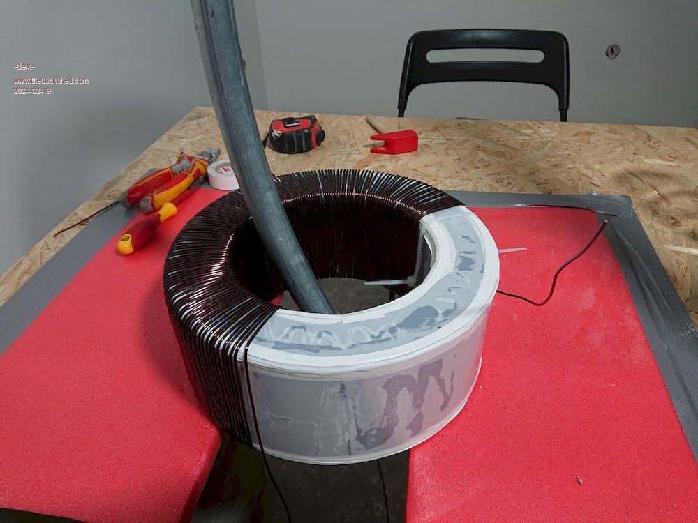 |
||||
Revlac Guru Joined: 31/12/2016 Location: AustraliaPosts: 1277 |
Looks like a good start.  Cheers Aaron Off The Grid |
||||
| rogerdw Guru Joined: 22/10/2019 Location: AustraliaPosts: 955 |
That is looking good Dex and I like that the core has nicely chamfered edges. Is the core a "standard" part that you bought ... or did they wind it to your request? I used 1.8mm wire and did wonder just how much harder 2mm would have been. I have used 2mm on some motor cycle coils many years ago and they were hard to wind being relatively small and fiddly ... but these big toroids are heavy enough to stay in place while we pull and stretch the wire around. I would not be afraid to try 2mm or maybe even 2.5mm. Cheers, Roger |
||||
| -dex- Senior Member Joined: 11/01/2024 Location: PolandPosts: 104 |
Thanks. The steel core was wound for my request. The weight and price increase with the wire diameter. Unfortunately, I had to buy this copper wire, but for the primary winding I have a large U-shaped transformer with a thick wires. I'll diasemblly them and then I just need to find a way to straighten this bent wire. 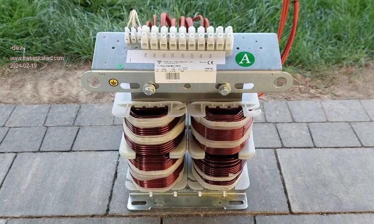 |
||||
| rogerdw Guru Joined: 22/10/2019 Location: AustraliaPosts: 955 |
Wow, that is a very nice supply of wire on that transformer. I'm not sure how others would do it ... but I would anchor one end and wind it out ... then I would go along and use my thumbs to bend it as straight as I could get it. Unless I absolutely had to, I would not use any mechanical tools in the process as I'd be too worried I might damage the enamel. And it doesn't seem to have any severe bends ... except maybe all the way inside ... so I would be hopeful it will be relatively easy to do. I know some would stretch it tightly ... which does help a little ... but I don't know if that does any damage. But by the time you've wound the secondary, you should be able to accommodate some imperfections in your primary. I was surprised at the hole size of your toroid ... it seemed very large. At least you shouldn't run out of room for your primary.  Cheers, Roger |
||||
| -dex- Senior Member Joined: 11/01/2024 Location: PolandPosts: 104 |
I took a closer look at this large U-shaped transformer and it turned out to be an aluminum winding  I have to find another one. I have to find another one.The first winding was covered with varnish and then wrapped twice with thin Kapton tape. I put quite a lot of it because the gaps are quite large, it takes a long time to dry, but I think it is enough to stiffen it. Now I winding the second layer. The target is 223 turns per layer 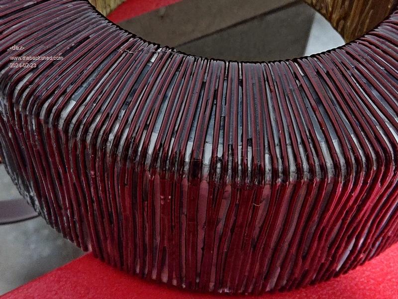 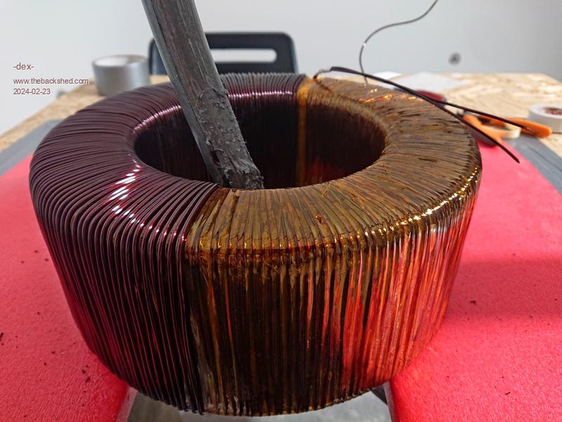 Edited 2024-02-24 06:07 by -dex- |
||||
| Page 1 of 9 |
|||||
| The Back Shed's forum code is written, and hosted, in Australia. | © JAQ Software 2026 |
