
|
|
Forum Index : Electronics : Time for a new Warpinverter build - #3
| Page 1 of 6 |
|||||
| Author | Message | ||||
| rogerdw Guru Joined: 22/10/2019 Location: AustraliaPosts: 955 |
Hi guys, I figured it was time to update my Warpverter story seeing it’s been dragging on for years. Lots of family stuff, work, wasting time on the net and generally dragging my feet. Has been two previous threads starting from three years ago. Time for a new Warpinverter build ... covers the transformers Time for a new Warpinverter build #2 ... covers the circuit boards etc Anyway, because I’ve never had solar here and was starting from scratch, there’s been a huge amount of other preparatory work to be done as well. I’ve spent a fair bit of time, effort and money fitting railing for 48 panels on the shed roof … and so far have mounted half of the solar panels … 24 x 275 watt and with a further 24 x 250 ones to go. 12.6kW all up … all second hand. I’ve built four MPPT units based on Poida’s project and modified a version of wiseguy’s board. I enlarged it and fitted both nanos across the bottom to have it all on the one pcb. I’ve done the setups and apart from a couple of initial niggles I’ve got 3kW of panels into each of the first two. There’s been a lot of work building the mechanical side of the housing for the mppts and also for the Warpverter. 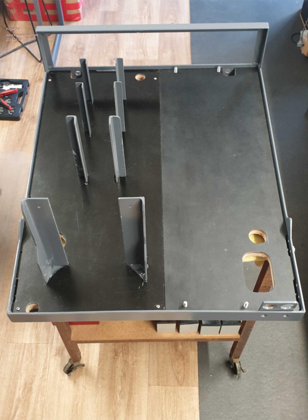 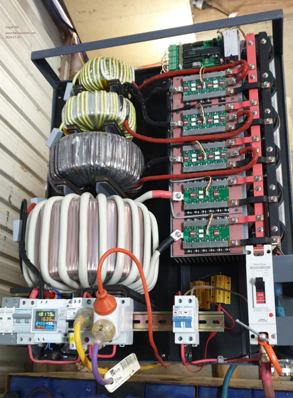 I finally raised the courage to hook up the warpverter and try it out, promptly blowing up half a dozen mosfets on one bridge. On inspection I discovered I had not soldered all the legs on one of the optocouplers … whoops, a bit embarrassing. And then soon after a further dozen mosfets on one of the large transformer half-bridges. There you go Klaus, I’ve joined the mosfet-blow-up-club.  At that point I woke up to the fact that I hadn’t really looked at the dead-time settings for the bridges … the time between switching off one half and turning on the other half … and discovered that it was set for around 200nS. I promptly replaced all the dead-time caps from 1nF to 10nF which increased dead-time to 2.3uS and so far so good. I struggled (read been too frightened) to keep raising the load but have gone from 15 watts, to 100, then 275, then 625, 825 and then 1,450 watts … 3,300 and now 5,200watts. The UPS batteries I was using along with a power supply topping them up was not really suitable for going much further than the 1,450 watts … so it was time for a forklift battery … something I’ve been planning on for probably 10 years. Cheers, Roger |
||||
| rogerdw Guru Joined: 22/10/2019 Location: AustraliaPosts: 955 |
I’ve mentioned this guy before … the local forklift sales and service guy … and I’ve rung him a number of times and he always says he’ll look and get back to me … but it’s never happened. So after lunch the other day I jumped in the car to visit him. He said that his supply has dried up and there was nothing around … but then he hesitated and said he did have one that he wasn’t sure about. Showed me this big brute, 48V and 980Ah and said he’d take it up the workshop and put it on charge and see what it was like … then let me know. I asked how much and he said “$500 … scrap value”. Sounded reasonable to me. Anyway as I was driving home I thought I should have just taken my chances and bought it on the spot coz I figured I wouldn’t hear from him unless I kept harassing him … so as soon as I got home I rang him back and said I’d take it and take my chances. Hooked the trailer up and went straight back over. At 1,330kg it was a bit much for my 7x5 trailer but I got home okay via the back roads and keeping a low profile. He even left the lifting strap on it so I could unload it and I took it back in the morning. My poor old David Brown tractor (that’s even older than me), wouldn’t look at lifting it no matter what I tried, so I wrapped a chain around the two c-sections in my shed doorway and fitted a block and tackle. I also used a length of heavy 90mm square steel post to prop under the cross piece so I didn’t bring the roof down. It all unloaded okay, but made a bit of a mess of the c-section. I’m a little embarrassed about that too. The battery was still sitting at 48.2v despite having not been charged and having been out in the weather for months. I gave it a charge using a couple of ex data centre COM10 battery chargers that I bought off Marketplace for $50 each. Good for up to 50 amps 45-54 volts … and 26 amps 55-65 volts (each). 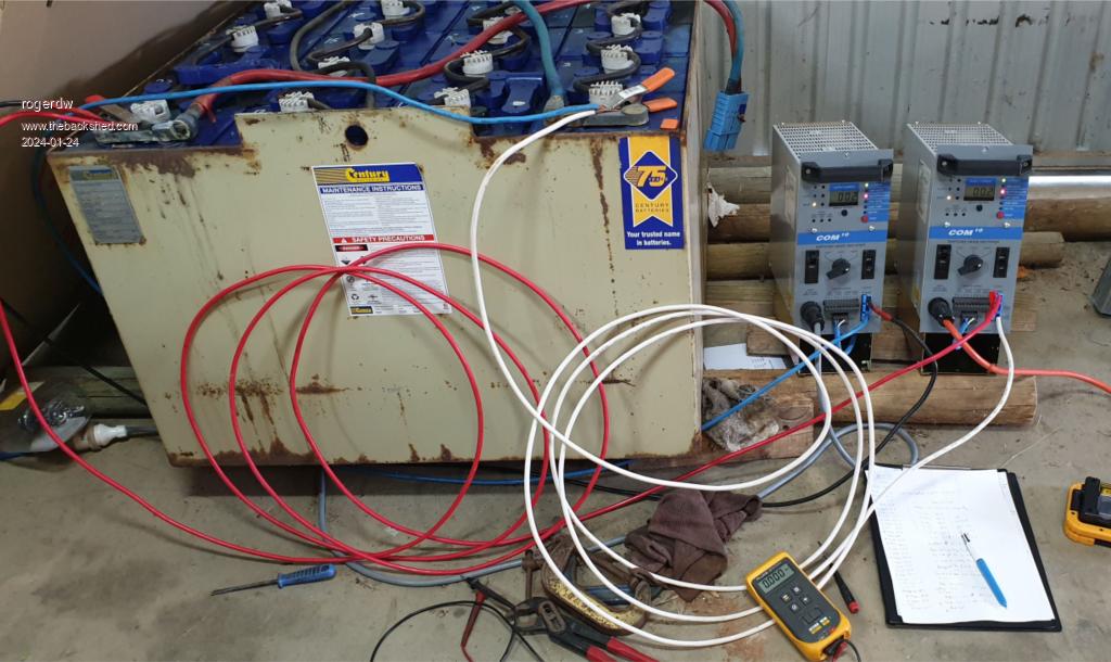 Cheers, Roger |
||||
| rogerdw Guru Joined: 22/10/2019 Location: AustraliaPosts: 955 |
I finally had to bite the bullet and really try out the Warpverter to do a decent discharge on the battery … so I fired up the pool pump … and then the pool heater pump … 1,800 watts combined. That’s the same pool pump that’s had a treadmill dc motor coupled to it and running directly from solar panels for the last three years. I was really apprehensive when I switched on the first pump and wasn’t sure what was happening while watching the power meter. The numbers were all jumping around and I didn’t hear any changes to the slight buzz the thing makes while idling. Then I just plugged in the second pump and still no audible change. I had to run outside to hear if the pumps were actually running, which they were. Phew! I ran it until the battery dropped to 46.3 volts … which took 12 hrs and 10 mins. Total kWh was 22.34kWh I then recharged it again which increased the specific gravity only a small amount and the next day discharged it using the same pumps but also adding a 1,500 watt heater for a total of 3,300 watts. Of course it discharged more quickly than the previous test … and when it got to 46.4 volts I switched out the heater. The battery volts increased for some time with the reduced load, and then eventually dropped to 46.3 where I switched off. Turned out it was virtually the same kWh as the first test … 22.86 After another couple days of charging and trying to raise the voltage more, I did a third discharge test. This time I added a kettle and boiled that a number of times ... bringing the load up over 5kW. I used Davo's trick of pouring boiling water over the weeds near my shed. Total power was 25kWh ... though it could have gone longer if I was prepared to run the batteries lower. 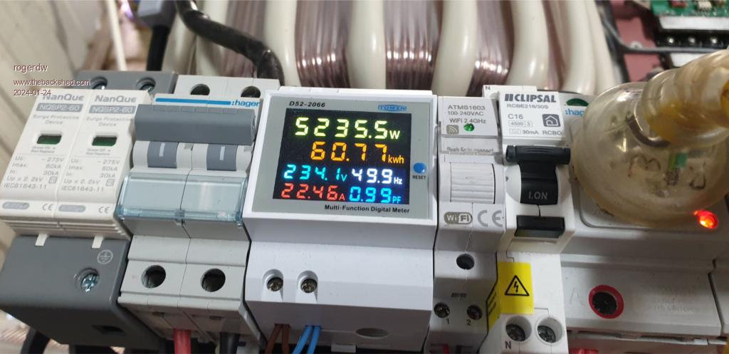 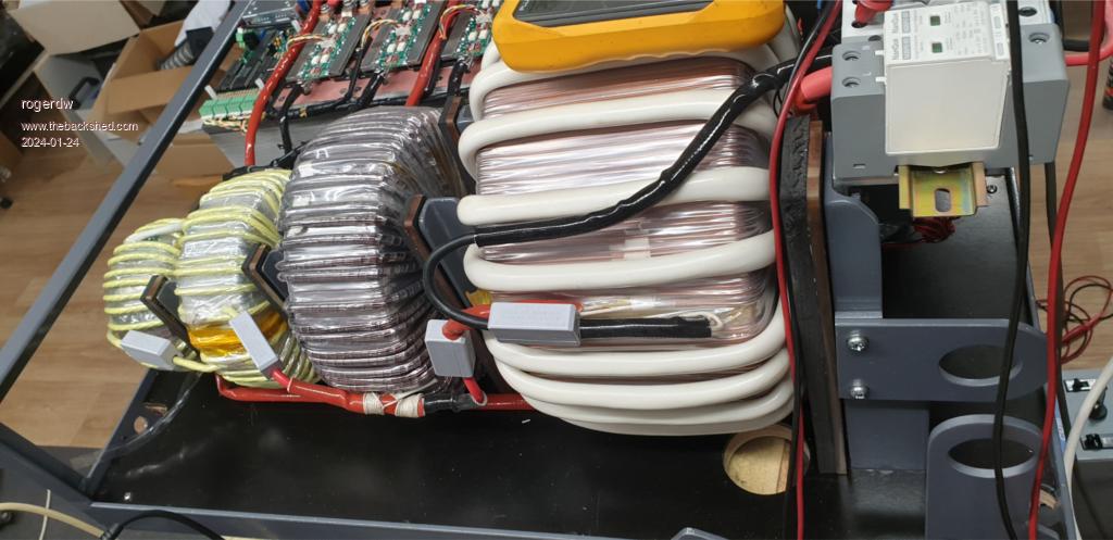 Edited 2024-01-24 23:36 by rogerdw Cheers, Roger |
||||
| Murphy's friend Guru Joined: 04/10/2019 Location: AustraliaPosts: 678 |
Well done Roger, glad you got it working and joined blow up club membership as well  . This complex design makes it rather too easy to make mistakes as I unfortunately discovered. . This complex design makes it rather too easy to make mistakes as I unfortunately discovered.I must have replaced about 100 HY4008's since first commissioning that beast of an inverter, no wonder I lost all faith in this design being very suitable for 48V battery banks. May your luck last longer. I would suggest HY5608's as replacement if you should have more mishaps, they are much more robust IMO. Just 8 of them start & run my caravan aircon (24V battery) no worries with my latest EG8010 mini inverter. |
||||
| Alston Regular Member Joined: 04/04/2021 Location: AustraliaPosts: 63 |
Roger that looks fantastic, great to see it up and running. What did you end up doing for your secondary windings, looks like welding cable for the biggest one? After getting my inverter running it has sat there for 6 months while I have been busy and only over the Christmas break did I assemble my controller which I have been programing this week. So this is the final piece I need fully complete it. Have you measured the idle current on yours? Klaus sorry to hear about you having issues again with your Warpinverter. Did you decide to try and bring it back to life or call it quits? |
||||
| rogerdw Guru Joined: 22/10/2019 Location: AustraliaPosts: 955 |
Thanks Klaus, I couldn't give up without trying it all out, especially seeing all the time and effort that went into it. I certainly acknowledge the sinking feeling you get when it goes bang and the feeling of hopelessness ... but then thankful for the ideas that kick in while trying to think through what might have caused it all. Tony suggested I could run up to tens of uSec dead-time if need be ... so if I have any strife, I may increase it from the 2.3uS I have now. There's a fair chance the 200nS I started with was the cause of my initial blowup. It has only clocked up about 85kWh so far, so a long way to go to be really confident ... but the more it runs the less aprehensive I am feeling. Wiseguy had also been suggesting the HY5608's so I do have a batch in the cart on the LCSC website already. Seems like good insurance to have a heap of spares. Then I need to finish off a couple spare modules to keep on hand. And thanks to you as well Alston. I had been wondering all along if you had finished yours yet, so good to hear it's still in the pipeline. You are correct on the welding cable for the primary of the large transformer ... 22 turns of 70mm2. I did cut off the outer orange sheath but it seems strong enough and the insulation between it and the secondary is pretty decent I feel. It would not have fitted without removing the orange either ... and there was room for just one more turn as it is. Nerve wracking! Just that 12 metres alone was about $340!!! Still if it all works ok long term, still a great investment. The medium tx has 11 strands of 1.7mm diam wire just wrapped with the clear mylar for the primary. It was a big job wrapping that length ... don't think I'd do it that way again. I'm not certain of the idle current now. One of the first things I did when I got it going was to measure the idling power ... and the control board and the 80-12V dc-dc converter and all the isolated supplies draw 6 watts ... and then combined was 31 watts ... ... but yesterday I measured it and it was looking more like 50 watts ... so I'm not sure what I'm doing different, other than running from the forklift battery and not just the small UPS batteries. And it was after I had changed the caps to lengthen the dead-time because I was wishing I'd measured it before to see if there was a difference. Need to get serious and look again. So good luck applying the finishing touches, I hope it goes well. If in doubt, increase the dead-time to be on the safe side ... you can always explore the extremes once you've had it going for a while and have more confidence. Cheers, Roger |
||||
| Murphy's friend Guru Joined: 04/10/2019 Location: AustraliaPosts: 678 |
Paul, my warpinverter is in pieces now and its very unlikely I will put it together again. Especially since the big dual core transformer is very easily converted to a 6KW EG8010 or nano based inverter. Just needs the primary off it, add 10 turns to the secondary and re wind the primary to a 9:1 turns ratio. Lots of other parts are recyclable as well. PCB's for this are already in the making. I'll do a post of that conversion when its ready. Good luck with your warpverter, mine proved to be a giant headache all the way. Roger, 50W idle is a bit on the high side, I seem to recall mine was around 30W when it ran. |
||||
| Alston Regular Member Joined: 04/04/2021 Location: AustraliaPosts: 63 |
$340 for 12m  that is insane, I bet you were nervous doing that one. Very interested to hear how you get one with that forklift battery. Like you I have no existing setup so this will all be new for me and I don't yet have big battery bank. that is insane, I bet you were nervous doing that one. Very interested to hear how you get one with that forklift battery. Like you I have no existing setup so this will all be new for me and I don't yet have big battery bank. How did you decide on how many KWs for your inverter? Do you have a large amount of current draw at your place or the need to start large motors? Thats a shame Klaus but at least it can all be mostly reused in a new inverter, I am sure it has driven you a bit crazy. Have your blow up issue always been at start up or also while it's running? |
||||
| rogerdw Guru Joined: 22/10/2019 Location: AustraliaPosts: 955 |
Alston, by the time I had to do that primary I couldn't bring myself to try and combine 30 odd strands ... and I had already bought some secondhand welding cable but I wasn't able to seperate the orange sheath from the inner layer ... so I just resigned myself to spending the money. At least it was nice to work with. I miscounted and wound one more turn than necessary and only just had enough room and just enough length ... but once I doublechecked I unwound the turn and had a couple of feet to cut off. I don't know that I really decided how many kW I wanted ... I just went a bit crazy making as large a core as I could ... then worked out the windings from that. Eventually it turned out that the secondary would be able to handle 60 amps, so I just went with that. I definitely didn't understand the whole thing before I started, otherwise I would have reigned it in a fair bit ... and once I understood I could use additional grid tie inverters with my own "minigrid", I realised I'd made it far bigger than necessay. We don't really have an extraordinary power requirement, though when I first started we had house full ... then a couple of the kids left ... then my MIL came to live with us. I do have a large sawbench and welders etc, though they don't get used hugely ... and we also have a couple ovens that often get used together for bigger gatherings. We also have a huge 15 year old ducted airconditioner that it would be nice to use on the odd occasion too. I really just wanted to avoid having to restrict power use because as easy as it is for me to gauge what sort of load I might be using at any particular time ... I'm afraid no one else here has any clue ... or any interest in knowing for that matter. And I'm past the angst of trying to teach or enforce any new rules. At one stage Tony had explained that the Warpverter could be built to pretty much any proportions because of the low switching frequency. I figured I might as well try out his theory. Cheers, Roger |
||||
| Murphy's friend Guru Joined: 04/10/2019 Location: AustraliaPosts: 678 |
Mostly startup problems, often caused by myself not thoroughly checking everything at least 3 times after I'd fixed a previous problem. One running mishap occurred after it's been running for months and I thought it's finally fixed, one day it decided back charging was not on, made horrible noises and blew before I could shut it down. Another time I had a very odd sine wave before it blew. That took some time to track down, turned out one of the 16 resistors on the control board that go to the opto drivers became open circuit - very strange. Be assured that beast will keep you on your toes |
||||
| Alston Regular Member Joined: 04/04/2021 Location: AustraliaPosts: 63 |
I don't blame you, I wound 15 strands for mine but if I were to do it again I would take you approach and made the hole in the middle bigger so I could use welding cable. I definitely understand your point about others in the house not caring/knowing about sharing the load over time. Well you should definitely be proud of what you have produced, a work of art! |
||||
| rogerdw Guru Joined: 22/10/2019 Location: AustraliaPosts: 955 |
Opening up the centre of my toroids was mostly wasted by me fitting a spacer to provide a bigger gap between the secondary winding and the core. I intended to add a similar spacer between the sec and primary ... but I realised I didn't have enough room in the end. Whether the extra spacing would have prevented the interference or not, I'm not sure ... I'm kinda doubtful. Thanks for the kind words about my work, I'm really pleased with how it's turning out. Sometimes I wonder if I would just finish it regardless, it might not look as flash ... but I'd have had an extra years use out of it maybe. And you have to be happy with yours too ... it certainly looks the part and definitely doesn't look like it's just been thrown together. Cheers, Roger |
||||
| rogerdw Guru Joined: 22/10/2019 Location: AustraliaPosts: 955 |
As I mentioned over on Alston's thread, I wasn't really sure if having a spacer between the core and the first windings (secondary) made much of a difference, but Tony is confident it will have reduced the spikes and inteference lines somewhat and was worthwhile doing. There was still enough inteference that I wanted to address it still ... so before I just caved in and bought a 60 amp EMI filter I decided to try an electrostatic shield first. I figured it should be easy enough as I had plenty of the shielding strip from the unwound Aerosharp toroids ... but as Tony pointed out ... putting a hundred turns around the thing is just like a hundred turns of wire and even with the earth tapped off near the centre, the ends would have quite high voltage on them. Seems the only way to do it properly is to create a shield like Klaus and Mark did quite some time ago, out of sheet copper. Anyway, I rolled out the big transformer and removed the primary winding and set about wrapping the thing. I'd bought a 3.5 metre roll 100mm wide by .1mm thick as well as 1 metre of 200 x .1mm off ebay. I made two big "washers" by soldering three strips together and cutting out for the top and bottom. I cut tabs all the way around so I could fold over the edge and solder to a 100mm wide strip wrapped all the way around the outside. So that I didn't create a shorted turn, I wrapped a few layers of mylar around the outer copper and then taped with kapton tape. I used all of the 100mm wide sheet and then cut just a few narrow strips from the 200mm wide roll to join top to bottom through the hole. Because I cut and folded tabs there too ... there were a few minor gaps, so I covered them with some adhesive copper tape I had lying around. 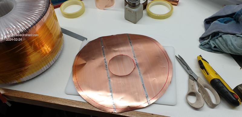 Pre-tinning the edges made life much easier when I went to join them ... reheat with the iron and fold over with a heavily gloved finger, which kept it nice and tight 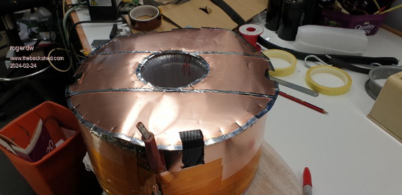 You can see the adhesive tape used at the exit of the centre hole which covered a lot of untidiness. 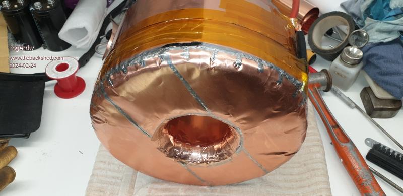 Cheers, Roger |
||||
| rogerdw Guru Joined: 22/10/2019 Location: AustraliaPosts: 955 |
Edit: I forgot to mention I wrapped the copper in mylar before fitting the primary back on. Then I had to rewind the primary ... 22T of 70mm2 wire!!! And of course the wire wasn't quite long enough despite my efforts at stretching it as tightly as possible all the way ... so I had to join on 5 inches to reach the terminal. Fired it all up and really couldn't notice any difference to the output waveform. I tried a few configurations of where and how to earth it ... but it didn't change. Tony offered a few suggestions of other places to tie in to the earth as well ... so I still need to try all those things. In the meantime I bought a 60 amp EMI filter from element14 and mounted it ready for when I try again. See here ... The element14 picture shown is of the baby brother ... the one I got was freakin' huge ... 245mm long by 85 x 60mm. One good thing was it has terminals to suit 16mm wire ... so I didn't have to fit ring terminals and then try and insulate them to keep it all safe. There was only one place that it could fit and it went in snuggly, touching all the way around ... but I still decided to get in there with the angle grinder and die grinder to create some clearance around the terminals. Fitted well in the end. 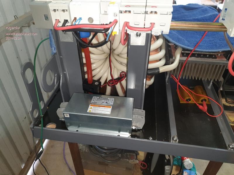 Edited 2024-02-24 23:23 by rogerdw Cheers, Roger |
||||
| rogerdw Guru Joined: 22/10/2019 Location: AustraliaPosts: 955 |
It's been a busy day today and I finally got the thing up on the wall. I had my wife and lad out helping me too ... and you were right Klaus, it probably wasn't a good idea to mount it on the wall ... but it's there now. I pulled out the largest toroid before we put it up ... and man was it a struggle even with that out. Then my wife went on shift so I lined everything up and lifted in the big one!!! 57kg ... and it's been years since I've been in a gym. Lucky there were no OHS floating around either. The cables back to the meter box are routed and ready to be connected, so will call my electrician mate back on Monday. Getting close. I've run it a lot already (before mounting it on the wall) and it's clocked up 350kWh so far. The pool doesn't know what hit it ... the pumps been run all day and almost every day ... and for the first time in 10 years I turned on an airconditioner in my workshop on a couple of hot days. I still have to fit the fan ... it's one I pinched out of an old airconditioner ... a barrel fan virtually the full width of the inverter ... and will blow up through the toroids as well as through the heatsink ... but I don't think it will be needed very often because it seems to run pretty cool so far. In fact even on hot days I didn't measure anything much over a couple degrees above ambient. Oh and I ordered a kilovac solenoid that I'll fit behind the circuit breaker as just one more line of defense if it needs to be shut down in a hurry ... and of course I'll need to build a controller of sorts for that too. 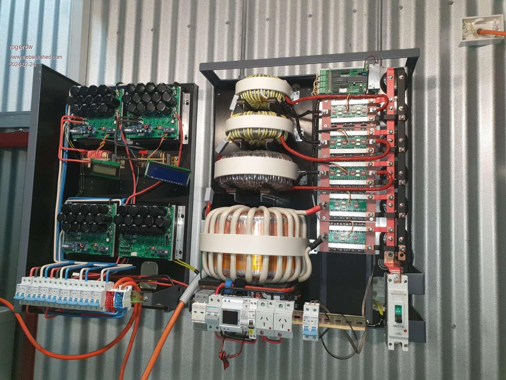 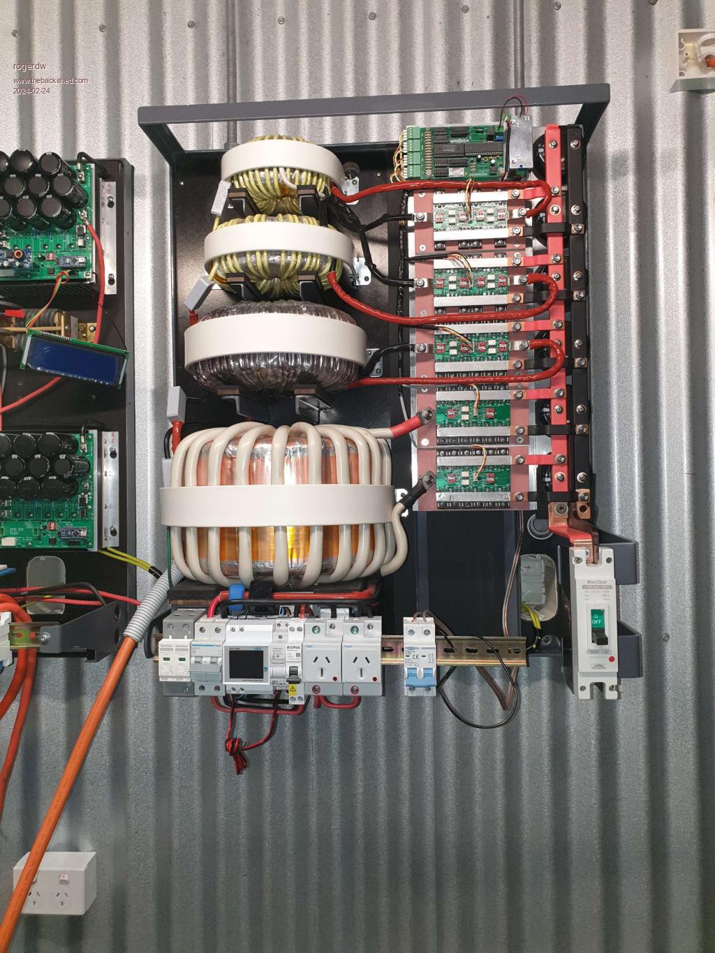 Cheers, Roger |
||||
| rogerdw Guru Joined: 22/10/2019 Location: AustraliaPosts: 955 |
The weight of the inverter is largely held by two 16mm threaded rods hanging from the landing of the stairs above ... and then bolted to the wall. It's all pretty substantial. My batteries are definitely staying on the ground ... and I built a little dolly for them so they can be maneuvered around if necessary. They won't be steerable (unless I use the crowbar again) but they roll extremely easily. I'm quite amazed seeing they weigh 1,300kg. Pity I can't post a video. It's bigger than it looks too ... they are 18" shifters. 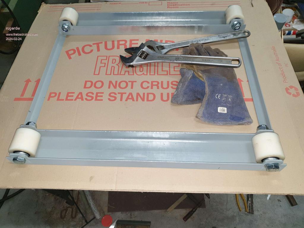 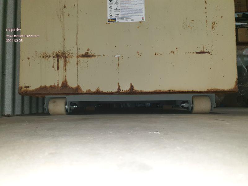 Cheers, Roger |
||||
Haxby Guru Joined: 07/07/2008 Location: AustraliaPosts: 426 |
Wow Well done Roger! I've been quiet over the last year as I have gone back to full time work. I thought I'd check in and see what's been happening. That is such a neat build. The half bridge boards, the welded brackets... Looks awesome! Does your warpverter also sound like a robot when the load changes? Or is it a constant "standard" 50 hz hum? |
||||
| rogerdw Guru Joined: 22/10/2019 Location: AustraliaPosts: 955 |
Hi Phil, thanks for the kind words and good to hear you still visit from time to time. It's finally all coming together which is about time ... too much time wasted on other useless stuff. It has a fairly quiet 50hz hum/buzz which doesn't really seem to change when the load changes, though I did notice a slight change when I went from non loaded to 2.5kW of motors. It's going to live in the next section of shed on from my workshop, and even while it was in the doorway on the trolley I could only hear it if there was no background noise ... and when I slid the door shut I couldn't hear it at all. I do hear the fan turn on in the charge controller, which I can just hear in the background. It's a little 12v barrel fan. So far it's been handy to know when the mppt's get warm enough to need a fan. Are you still using your Warpverter ... and did you ever finish your 3 phase one? Cheers, Roger |
||||
| Murphy's friend Guru Joined: 04/10/2019 Location: AustraliaPosts: 678 |
Oh my Roger, you really went to town with your warpverter build  . .And I thought mine was elaborate  . Well, since my warpverter no longer exists its yours that's on top of the hill now . . Well, since my warpverter no longer exists its yours that's on top of the hill now .Regarding that copper static shield, again you have bettered anything I have seen. I did not think it had much effect on my warpverter but I left it place when I re wound the big transformer primary for an EG8010 inverter. As I already have a similar 6KW inverter with an almost identical toroid, but no static shield, I should be able to see if it makes a difference with interference when I compare those two 6KW inverters. That is some time off as I'm still waiting for the PCB's for the second 6KW inverter. I cannot see any chokes in your warpverter so I assume there are none? Most of the noise my warpverter made came from the big 'swinging' choke I put there on Tony's advice. I'll try that choke in the new 6KW EG8010 inverter. |
||||
| rogerdw Guru Joined: 22/10/2019 Location: AustraliaPosts: 955 |
Haha thanks Klaus, been a long time coming. The shield was hard work and took some time but for a change I got stuck into it and got it finished. The .1mm was pretty thick really and it was good to work with because of the strength but it was nice to finish off with that adhesive copper tape being so thin and flexible. I will be interested to see the end result of the test with your tx with copper foil and without. I do wonder how the originals get away with the long lengths of ribbon shield as against our single turn. And you're right I don't have a choke in mine, Tony didn't seem to think it was really necessary so I didn't argue. One less task. The inverter does have a bit of a hum/buzz but it's certainly not excessive so I'm not concerned. I spent some time with a stethoscope to find out and strangely the medium tx seems to be the louder (the outer primary winding) ... followed by the large one. I'm slowly loading it up and hit it with the air compressor today. Was interesting to see the wattage creep up as the pressure built up. The electrician called in to check it all out and will be back in a few days to hook it up. Moment of truth coming. 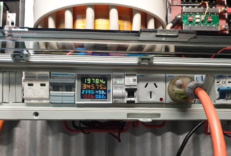 Edited 2024-02-26 18:00 by rogerdw Cheers, Roger |
||||
| Page 1 of 6 |
|||||
| The Back Shed's forum code is written, and hosted, in Australia. | © JAQ Software 2026 |
