
|
|
Forum Index : Electronics : Help needed to explain mishap with MPPT and BMS
| Author | Message | ||||
| gaspo Regular Member Joined: 25/06/2018 Location: AustraliaPosts: 67 |
I've built a small solar and battery setup to test components for an off-grid system. The setup includes three 250W solar panels connected in series and a 52V/50Ah lithium iron phosphate (LFP) battery. I've also built a 15A version of Poida's MPPT, which is connected to the battery with a BMS and a low-side MOSFET disconnect. Below is a simplified diagram of the connections. When both the load and charger low-side switches are on, the MPPT charges the battery. During testing, the solar input was about 95V, the PWM was set to 35%, and approximately 250W was flowing into the battery. There was no load connected to the battery. Issue 1: Unexpected MPPT Output When I turned off the low-side charger switch, the BMS showed 0A charging current. However, the MPPT displayed 350W of output power. My current clamp meter showed 0A on both the solar input and the battery input. When I turned the charger switch back on, the MPPT resumed charging at 250W. I have no idea where the 350W is coming from, perhaps the HAL sensors is affected somehow when the charger switch is off. Issue 2: Short Circuit and Component Failure This issue is more serious. After repeatedly turning the charger MOSFET on and off, I left it off for a minute or two. When I turned it back on, the battery's 40A DC breaker activated, disconnecting the battery due to a short circuit. As a result, the MPPT output Hall effect current sensor, MOSFET, and dual diode were all damaged. Can someone please explain the potential effects of turning off the low-side charger MOSFET on the running MPPT and why a short circuit might occur when turning it back on? Short charger disconnects (few seconds) did not cause failure before. Some photos of MPPT and the battery setup. 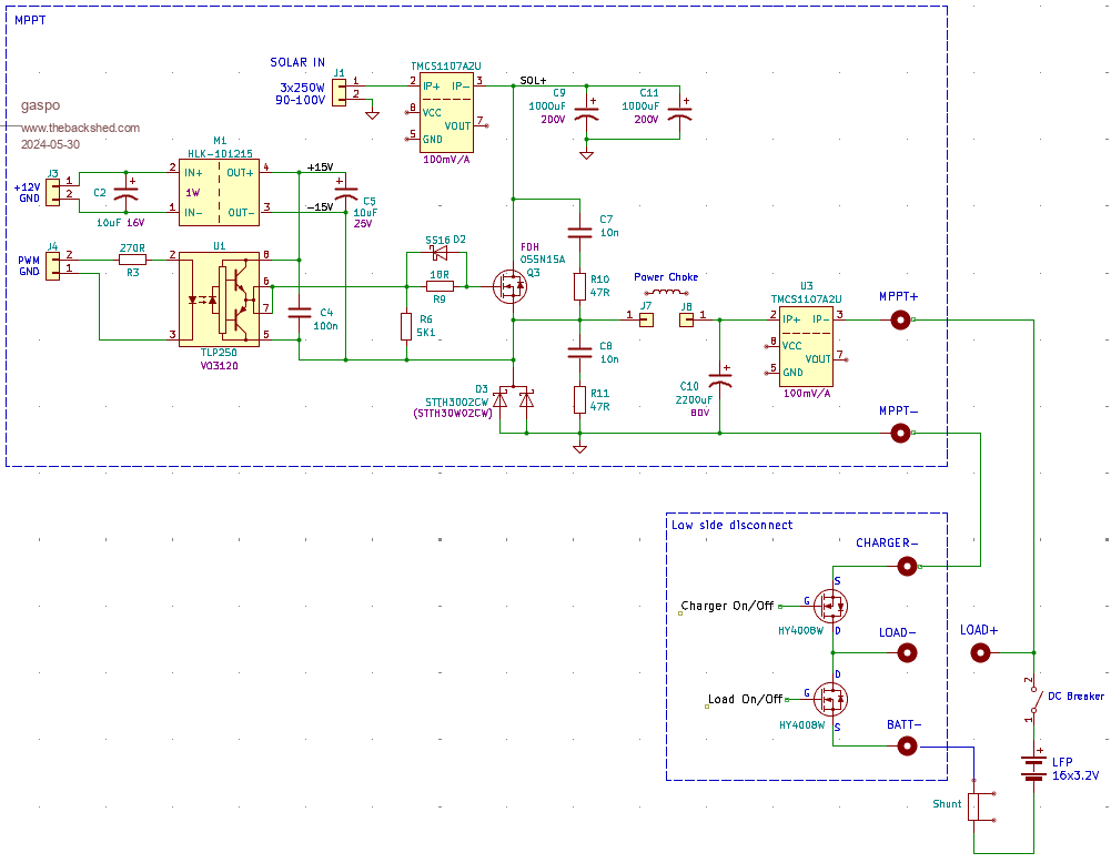 |
||||
| nickskethisniks Guru Joined: 17/10/2017 Location: BelgiumPosts: 477 |
Nice pics! Great implementation! How is the charger mosfet controlled? By hand or digital? Which firmware version do you use? Because of the abrupt battery disconnect, there is a possibility you've created an oscillation event between input/inductor/output capacitor, boosting the voltage up above breakdown voltage. The controller is rather slow to adjust the duty cycle when transients happen. You need to block the pwm pulses first and then you can safely disconnect the battery. In commercial controllers they don't allow you to do so, they recommend to disconnect solar panels first. Did your disconnect MOSFETs survive? They are only 80V rating, which can be just a bit on the lowish side? The panels it's open circui voltage can be on the controllers output when you do what you did. To kill your current sensor I can only imagine a current spike through the current sensor created by a potential difference between output cap and the battery. Perhaps a bounce on the gate of the disconnect mosfet? Edited 2024-05-30 07:09 by nickskethisniks |
||||
| Solar Mike Guru Joined: 08/02/2015 Location: New ZealandPosts: 1214 |
Suddenly removing the load from your mppt controller whilst running at a reasonable power output can result in the output voltage rising drastically and so damaging components not voltage rated for the potential increase. This situation can occur if the CPU feedback loop is too slow to react to the sudden load removal. Note the same thing happens if the controllers output fuse or circuit breaker pops. For my higher output controllers I tend to have a fast voltage sensitive switch (comparator) monitoring the mppt's output voltage, if an output fuse blows or someone accidently opens the output breaker the comparator acting independently of the CPU shuts down the PWM before the CPU has time to react. Best advice is place your mosfet switch on the controllers input PV side. Cheers Mike |
||||
| gaspo Regular Member Joined: 25/06/2018 Location: AustraliaPosts: 67 |
Thanks for the responses. Low-side disconnect mosfets are electronically controller via BMS's user interface. The BMS is my own design. Schematic of the disconnect switches: Low-side disconnect.pdf Yes, mosfet switches have survived. I thought that the low-side disconnect mosfets won't see higher voltage than the battery's max 56V. This could be it. The event happened when I have left charger off for few minutes and then turned back on while the MPPT PWM was still going. The short disconnect time for few seconds did not seem to be a problem as I have turned charger mosfet on/off several times. Was the diagram of your opamp PWM disconnect in of yours BMS posts? Many of the commercial BMS-es have lowside load and charger disconnect circuitry. I wonder how the MPPT charges (Victron, or various cheap Chinese brands) protect against being disconnected via BMS when there is no comms between them. |
||||
Revlac Guru Joined: 31/12/2016 Location: AustraliaPosts: 1277 |
I have a PCM60X in the shed on a old 150a DALY BMS 16s lifepo4 battery , the charge controller has put up with multiple BMS disconnects every day for a few years no problems at all, adding a active balancer helped with a cell that was a bit out, result was fewer disconnects and a happier system.  The charge controller can still see the battery voltage with the charge moss off, works a bit like a diode I guess, so its not a complete disconnect. If charging hard it could throw a fualt and the charge controller would disconnect the relay inside itself. Cheers Aaron Off The Grid |
||||
| Murphy's friend Guru Joined: 04/10/2019 Location: AustraliaPosts: 678 |
I'm curious why you want to switch the low side at all. In my set up the MPPT connects to the battery via an isolating C/B in case I need to remove the MPPT. In this case I *always* disconnect the solar input first. The MPPT regulates the battery charging so other than the above scenario I see no need for a mosfet switch to stop the charging as well - keep it simple .If you are worried about overcharging the battery in case of a MPPT fault, please read the 'kilovac' posts here. I just installed this and a voltage sensing relay that controls it. It will possibly never activate but it's like a pay only once insurance premium to me. With regard of the load on/off mosfet, assuming your load is an inverter (like at my place) I see also no reason for it. If you want to turn off your load just switch the AC inverter power and leave the inverter connected to the battery bank. Perhaps you could elaborate just what you plan to connect at the 'load' terminals. |
||||
| rogerdw Guru Joined: 22/10/2019 Location: AustraliaPosts: 955 |
Wow, that's next level design and layout there. Looks like you're going into production. And I love all the 3D printed gear and various colours ... finishes it off well. I'd be interested to know what version of firmware you're running too. Cheers, Roger |
||||
| gaspo Regular Member Joined: 25/06/2018 Location: AustraliaPosts: 67 |
If you are asking about the MPPT firmware version, I'm not using a Nano board. Instead, I built my own control board using an STM32 controller and wrote the code myself. mppt-control-stm32f303k8.pdf The low-side switches serve as a last-resort defense that the BMS can automatically deploy if the MPPT fails to stop charging or if the inverter fails to disconnect on a low battery. Under normal circumstances, both switches will always be on. I'll check out your 'kilovac' post. |
||||
| Murphy's friend Guru Joined: 04/10/2019 Location: AustraliaPosts: 678 |
Thanks for this explanation, the same happens in my set up but is done differently. As mentioned, the 'kilovac' relay covers the MPPT fail scenario. For low battery sensing, my control board simply switches the inverter off - it remains connected to the battery. With your mosfet switch you have to go through the capacitor pre charge routine before you can start the inverter again. |
||||
| wiseguy Guru Joined: 21/06/2018 Location: AustraliaPosts: 1296 |
What value of inductor are you using, what material is it. If you used a saturation tester on it what were the results ? What is the highest voltage at the solar input in normal full daylight with no load (or no PWM) on the mppt ? In theory the dual diode for the flywheel part of the cycle should be very robust and hard to kill - Dex was having issues with his mppt and I think he had used 200V Schottkys but the mppt still killed them, then he tried silicon carbide types and last I heard they were working fine, the lowest SiC diode reverse voltage was around 600V. I'm a little perplexed about the charger and load switching and why it is configured that way. For instance if the circuit breaker is open then turning on the charger FET, it turns on the load - the solar is applied to the load minus the battery ? If it is charging and you turn the Load off it stops charging but the load is still be powered by the MPPT. Why is the Load switch not in the Load return lead ? I am not saying anything is wrong with the configuration only that it is not obvious to me what it is up to. If at first you dont succeed, I suggest you avoid sky diving.... Cheers Mike |
||||
| gaspo Regular Member Joined: 25/06/2018 Location: AustraliaPosts: 67 |
Inductor is some ferrite material salvaged from a broken inverter, Φ22x47mm, height 38mm, 23 turns, 150uH and saturates between 26-40A - hard to tell because of shallow curve knee. The panels Voc = 110-115V. When the battery circuit breaker is open, the BMS power is off, which also turns off both the charger and load switches. The operation of the charger and load low-side switches can be explained by the following diagram: 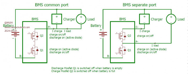 More details here: Low-side-port-disconnect.pdf Edited 2024-05-31 18:20 by gaspo |
||||
| The Back Shed's forum code is written, and hosted, in Australia. | © JAQ Software 2026 |
