|

|
Forum Index : Microcontroller and PC projects : Armmite H7 5V Tolerance
| Author | Message | ||||
| PhenixRising Guru Joined: 07/11/2023 Location: United KingdomPosts: 858 |
I get the impression from the manual that other-than the DAC outputs, the pins are 5V tolerant(?). Yet reading the STM manual, it states that the pins are 3.3V. What am I missing? |
||||
| matherp Guru Joined: 11/12/2012 Location: United KingdomPosts: 9115 |
All pins with analogue capabilities must be limited to 3.6V maximum. See the datasheet FT vs TT pins |
||||
| Mixtel90 Guru Joined: 05/10/2019 Location: United KingdomPosts: 6787 |
According to the RP2040 specification all pins on the Pico are 3V3, with an absolute maximum of 3V6. However, Raspberry Pi have said that the pins will *withstand* 5V. That doesn't mean they are suitable for 5V systems, as they can provide over 5V and remain in spec. You pay your money and you take your choice. My own preference is to keep to the spec - 3V6 absolute maximum. At least on anything that I want to have running for any length of time. :) Mick Zilog Inside! nascom.info for Nascom & Gemini Preliminary MMBasic docs & my PCB designs |
||||
| matherp Guru Joined: 11/12/2012 Location: United KingdomPosts: 9115 |
Mick - check the thread title  |
||||
| Mixtel90 Guru Joined: 05/10/2019 Location: United KingdomPosts: 6787 |
OOPS..... :) Mick Zilog Inside! nascom.info for Nascom & Gemini Preliminary MMBasic docs & my PCB designs |
||||
| PhenixRising Guru Joined: 07/11/2023 Location: United KingdomPosts: 858 |
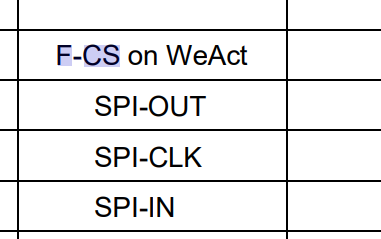
For SPI, I should be OK with a 5V device then. I have a WeAct and just wondering what F-CS is?  |
||||
| matherp Guru Joined: 11/12/2012 Location: United KingdomPosts: 9115 |
Chip select for a flash chip that may or may-not be fitted |
||||
| PhenixRising Guru Joined: 07/11/2023 Location: United KingdomPosts: 858 |
Dammit, I was trying to think of everything that begins with 'F' before asking  |
||||
| disco4now Guru Joined: 18/12/2014 Location: AustraliaPosts: 896 |
It looks like the gitHub site for the WeAct H7 100 pin board is gone. Here is the schematic for it I have previously downloaded. STM32H7xx SchDoc V11-WeAct100.pdf I have not looked to see if F-CS has a pullup, if not you will need to set it high as the flash is sitting on SPI. From the H7 manual for WeAct board. Latest F4 Latest H7 |
||||
| PhenixRising Guru Joined: 07/11/2023 Location: United KingdomPosts: 858 |
Thanks Gerry, I wanna build my own board (doesn't matter which variety) so this could be useful. Don't know if this belongs in the manual-corrections thread but you have illustrated above, why I had to ask about 'F-CS'. It is shown on the table with a hyphen but naturally, a search of the manual found no explanation because elsewhere it has an underscore 'F_CS'. Loving this H7. Currently have 150mm dupont wires between the WeAct and a SPI device. Happily talking @ 20MHz  Anything above that and I get bad data. Very impressive though. SPI READ into an array (32bits) is also much faster than the 4-read method.  |
||||
| Volhout Guru Joined: 05/03/2018 Location: NetherlandsPosts: 4233 |
PhenixRising, I would never rely on 5V compatibility of IO pins if I was making a new design anyway. There is minimum cost involved to add a level shifter. And there are plenty of them. It makes it so much more robust. Volhout PicomiteVGA PETSCII ROBOTS |
||||
| PhenixRising Guru Joined: 07/11/2023 Location: United KingdomPosts: 858 |
Hi Volhout, The device will actually run on 3.3V so I'll probably switch to that. What is not clear to me is that if the device is running on 3.3V, will the EncA, EncB and EncI inputs still be okay with 5V from the encoder. counter-click-manual-v100.pdf |
||||
| disco4now Guru Joined: 18/12/2014 Location: AustraliaPosts: 896 |
Now corrected in the source document so will be fixed in the next update. Latest F4 Latest H7 |
||||
| Mixtel90 Guru Joined: 05/10/2019 Location: United KingdomPosts: 6787 |
I'm not familiar with the chip, but if it has a pin for the IO supply then you may find that inputs must not exceed the voltage on that pin - no matter what the specified maximum is. That's because any protection diodes will probably go to that pin rather than VCC. Mick Zilog Inside! nascom.info for Nascom & Gemini Preliminary MMBasic docs & my PCB designs |
||||
| PhenixRising Guru Joined: 07/11/2023 Location: United KingdomPosts: 858 |
Now corrected in the source document so will be fixed in the next update.  Also, in a paragraph pertaining to the library topic, "existance" needs correcting. Having lots of fun with this H7, Gerry. Getting all kinds of ideas.  Not critical but I really like SYNC on the Picomite. Not possible with ARMmite H7? |
||||
| PhenixRising Guru Joined: 07/11/2023 Location: United KingdomPosts: 858 |
"Adaptor" should be adapter.  |
||||
| PhenixRising Guru Joined: 07/11/2023 Location: United KingdomPosts: 858 |
5V Tolerant (FT) en.STM32G0-System-General-purpose-IO-interface-GPIO.pdf |
||||