 |
|
|
|
Site Navigation
Projects & Information
»General Information»Wind turbine Projects »The F&P Smartdrive »Electronic projects »Microcontroller projects »Miscellaneous Kits & Parts
»Basicly Natural Pty Ltd»PVC & Aluminium blades »Scale model farm windmills »Price Watch Discussion Forums
Handy Links
»Wind»Solar »Electric Vehicles »Electronics »Micro Controllers »General Interrest About TheBackShed Getting Started Privacy Policy Expanded Scale Voltmeter
LCD Panel Meter
|
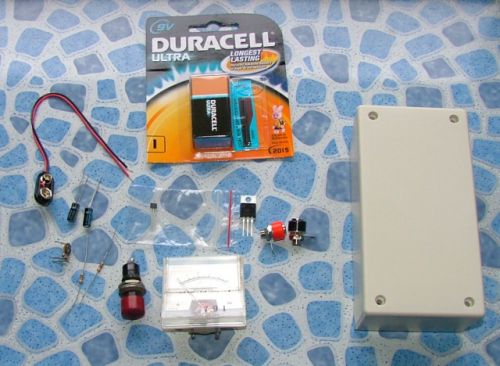
The collection of bits.
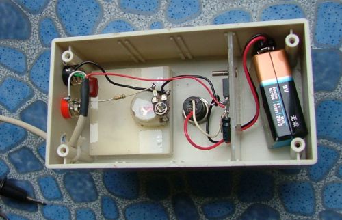
Mounted in the box. As there are only a few components, I decided not to use a circuit board. The 9v battery is kept in its own little cell so it cant bump into the other components. I used a couple of banana sockets as my test points.
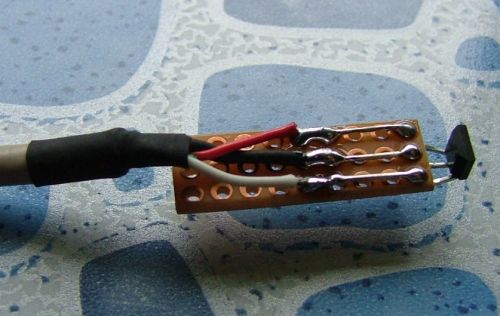
Below is the hall sensor mounted on some experimentors board. I've bent the sensor so its back is facing out.
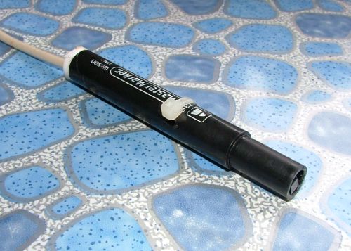
The sensor and board mounted into a old pen. The back face of the sensor is level with the opening of the pen. A cable tie holds it in position.
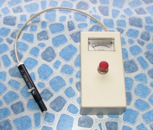
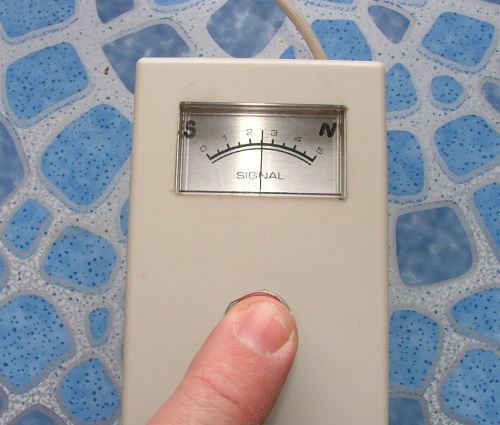
The completed Gauss Meter.
To calibrate, press the power butting and adjust VR1 so the meter reads dead center. This is our null, or 2.5v, point. Make sure there are no magnets near the hall sensor while you do this. I've marked on the meter scale a S and N, so I know which magnet pole I have the sensor facing.
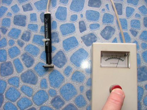
Testing with a small NEO magnet, N pole.
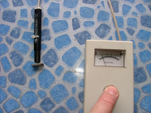
And S pole
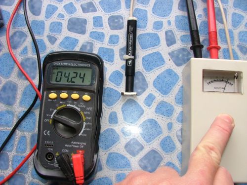
If I want to accurately measure the Gauss, I plug in my digital multimeter to take an accurate voltage reading. In this example, I'm reading 4.24 volts. So its a N pole, and its 1.74 volts, or 1740mV, above our null point. 1740 / 1.3G = 1338G, which is about right for a NEO magnet.
|
||
