
|
|
Forum Index : Electronics : Inverter building using Wiseguys Power board and the Nano drive board
| Author | Message | ||||
| KeepIS Guru Joined: 13/10/2014 Location: AustraliaPosts: 1399 |
FYI If you are using the MP-K78U12 DC/DC Converter 48V to 12V 500mA module for the Nano controller, it's available from au.element14.com in a right angle pin mount: DC-DC module This is the right angle pin version, but leads should straighten with care? the straight Pin version seems to be on back order everywhere. This can be omitted if you are using an external 12v supply source. I and others often use isolated DC-DC supplies. But these small units make for a neat installation. You would need a separate 12v source for Fans though, this is a good idea in any case, I really don't like sharing the Nano and Power board 12V supply with any external devices. This straight pin device is likely available elsewhere, but this is what I found, so sharing. If anyone knows of, or can see a problem with using these, then please share. It's all too hard. Mike. |
||||
| wiseguy Guru Joined: 21/06/2018 Location: AustraliaPosts: 1016 |
Digikey has 664 of the K78U12-500R3 (straight pin) in stock they also have the 70 of the K78U12-1000R3, 1A version. I do agree that to straighten the pins on a right angle version is probably easy too if required. I would expect builders to try to consolidate to 2 or 3 suppliers ie Digikey, LCSC, Farnell and as much as possible juggle around to take advantage of their $50/60 value for free delivery (not LCSC - no free delivery with them). I expect that Capacitors etc will probably be needed for the Cap board so hitting the Digikey min for free delivery is easy. BTW I have found that with Digikey if you need to spend $59 on parts, you would need to pay $59 + $24 delivery, total for the order ~ $84. So you can now buy an extra $25 of stuff essentially to the same value of $84. and the $25 worth of the parts was no extra for the total cost ($84 inc free delivery). Just to clarify, if you spent an extra dollar to bring it to $60 it costs $60 instead of $84, but its like my wife going shopping, I can put the parts on the table and say look I saved $25 when I spent $84  Edited 2024-03-13 15:58 by wiseguy If at first you dont succeed, I suggest you avoid sky diving.... Cheers Mike |
||||
| KeepIS Guru Joined: 13/10/2014 Location: AustraliaPosts: 1399 |
Hi Mike, this morning I tried to get the 1A versions showing 70 in stock, but the order comes up with a message saying that all items on my order are on back order. I've sent an email to them so I'll see what happens. Yes I often able to adjust the quantity to balance out the cost of freight as well on other parts, a number of outlets do that now, certainly gives you best bang for the buck on some items. Digikey Link . Edited 2024-03-13 16:29 by KeepIS It's all too hard. Mike. |
||||
| Murphy's friend Guru Joined: 04/10/2019 Location: AustraliaPosts: 600 |
Mike, you may not know that if you order PCB's from JLC and immediately after that order you order electronic parts from LCSC then that parts delivery is free. |
||||
| wiseguy Guru Joined: 21/06/2018 Location: AustraliaPosts: 1016 |
Hi Klaus, you are right I did not know this and could have capitalised on it multiple times. How do I get the two related ? I know they are affiliated but The LCSC site and the JL sites dont seem to be up front about this. So as they are different websites how do I tie the parts order with the JL PCB order? Thanks for the hint it will make quite a difference to me as I place lots of PCB orders but only order from LCSC when desperate (Hy5608) and a few other exclusive parts other than that I avoid them like the plague their freight is really expensive for small orders. Had another look, can you confirm that you just order the parts from JLPCB in their "parts" section, which seems to reflect the LCSC listings. ie you dont order on LCSC only JL ? Edited 2024-03-13 21:10 by wiseguy If at first you dont succeed, I suggest you avoid sky diving.... Cheers Mike |
||||
| Murphy's friend Guru Joined: 04/10/2019 Location: AustraliaPosts: 600 |
Mike, this was discussed on the forum quite some time ago which is why I know. I recently ordered some PCB's from JLPCB and I also needed some HY5608's, so after ordering the PCB's I went to the *LCSC parts* section and ordered the mosfets. When I got to the shipping part I was informed that was free. I have never ordered any parts from JLPCB, had no idea one can do that. On a previous order I ordered the LCSC parts first, selected the shipping option, paid for that too and then got around to order PCB's. That time the shipping option for those PCB's was not free. I have no idea why, perhaps you can discuss that with the nice lady on their chat section. I usually pick their cheapest shipping option, being a poor pensioner, and I don't mind waiting two weeks for the boards to arrive. While the PCB's & parts were ordered at the same time, the parts arrived two days before the PCB's, so they are shipped separately. |
||||
| wiseguy Guru Joined: 21/06/2018 Location: AustraliaPosts: 1016 |
Thanks Klaus - I think I will take your advice and ask the chat person, I usually find Troy or Spencer and another chap - where are you hiding the nice lady  Maybe you contact them at more civilised hours.... Edited 2024-03-14 00:09 by wiseguy If at first you dont succeed, I suggest you avoid sky diving.... Cheers Mike |
||||
| KeepIS Guru Joined: 13/10/2014 Location: AustraliaPosts: 1399 |
Got an email and a conformation that the 1A DC-DC supplies have been shipped It's all too hard. Mike. |
||||
disco4now Guru Joined: 18/12/2014 Location: AustraliaPosts: 844 |
LCSC shipping discount. I just order parts. I have some PCBs from JLPCB on the way($5.00 with shipping).I did not link to LCSC from the JLPCB web site but at checkout it said I had a PCB order and reduced shipping from $16.50 to about a $1.50 . Said it could not be free because of different customs declaration or something like that, but would be discounted. Gerry Edited 2024-03-14 17:04 by disco4now Latest F4 Latest H7 |
||||
| KeepIS Guru Joined: 13/10/2014 Location: AustraliaPosts: 1399 |
Hi Gerry, good to know, btw my last order from LCSC just arrived, got here in about a week. It's all too hard. Mike. |
||||
| KeepIS Guru Joined: 13/10/2014 Location: AustraliaPosts: 1399 |
A teaser photo, I could not help myself This board by Wiseguy is really easy to build and it looks great, a lot of thought has obviously gone into this. I'll go over everything to be sure something was not missed, but so far it looks correct.  . It's all too hard. Mike. |
||||
| KeepIS Guru Joined: 13/10/2014 Location: AustraliaPosts: 1399 |
Just an update on the progress of the Controller and my build. I've modified some old older code by Poida and have this doing most of what it's supposed to do - I think - so the controller PCB is fine no changes except for one tiny link. Wiseguy mentioned that the Nano silkscreen was back to front, so the USB port on the Nano should face the edge of the PCB, not face inwards as shown. That my soon change with the next PCB, but some of us have the current PCB and mine was not damaged when powered up back to front. Using the Nano for the controller is brilliant. IMHO it's worth getting the onboard 12V supply module, this is a real quality unit and worth it. I have been waiting for a few toriod rings and have had to take it easy for a few weeks, so a little behind in getting the final build done. I believe the Nano code from Poida is close to release, a lot of testing going on to make sure it's right, IMHO the Nano Controller it leaves the old 8010 based controllers in the dust, and I've used quite a few variations of the 8010 controller. Cheers. Edited 2024-04-04 13:25 by KeepIS It's all too hard. Mike. |
||||
| KeepIS Guru Joined: 13/10/2014 Location: AustraliaPosts: 1399 |
FYI The beta code has arrived for testing, hopefully once Poida is happy with his wonderful creation, and made any late updates (if needed), it should not be long before the release. All I can say for now is that it's looking really nice, and most of what I've thrown at it has not caused the slightest hiccup to the SPWM drive or the Power stage, in other words, it has not glitched under any crazy power supply condition. The operational status display is good, and if the inverter is not powering up, you usually have the reason displayed on the LCD, or by connecting the USB port to a Terminal program and streaming some more detailed status info. The data normally sent to the LCD can also be displayed via USB on a PC. All are selected from the Main settings menu which is accessed by the USB port and a Terminal program running on a PC. Tera Term for windows is what I'm using. I'm about to start building a second controller, I cannot wait to get that into the Main big Inverter. It's all too hard. Mike. |
||||
| KeepIS Guru Joined: 13/10/2014 Location: AustraliaPosts: 1399 |
On of the neat features in the Nano Code is a software current limit. The Over current settings in "Setup Menu" are for this Code over current trip. The main setting is for the current trip point, this is not to be confused with the Hardware over current trip and Reset button, the hardware AC over current setting is made via a 10 turn variable resistor. The current trip setting is for the software trip, it flashes the Run LED fast at the over current point and displays a * character after the "Trip" text on the LCD. As the current increases the Controller starts to ramp down the AC voltage and then after increasing current, it cuts the Gate enable to stop SPWM drive to the Power stage. It recovers itself when the current drops. All with soft ramp up/dn. Setting the cutoff to a high enough value obviously disables it. I guess the usability depends on your system, but it's a nice feature to have available and deserves more investigation when I get a full Nano system running in anger. Test Mode is brilliant: It allows you to run the Controller with no power board (drive lead unplugged) or run the power stage on a separate supply for testing independent of the controller. The system will run from 0Vdc up, the controller technically covers an inverter from 24v (18v) to a 48v (58v). I rectified an small error in my own test code that stopped it working correctly when an optional low voltage cutout I included was set to 0. Test mode allows you to run the controller with virtually nothing but a USB cable supplying 5v to the Nano, all under voltage cutouts are bypassed, but you can play with over current settings, look at waveform, adjust current sensors and etc.. With around 15v from a current limited power supply applied to the Inverter, and some smaller Power board Caps (less stored power), you can look at AC output, power board waveforms and test the complete system with it just loafing along. You could, on a first power up, slowly raise the DC voltage from around 15v all the way up to 54v **if your Toriod is wound for a 48v system** and monitor current, and even better if you can set the power supply for low current trip, it should save unexpected blowups, especially with minimal Caps, or even better, None, for a first run. Some really neat features included in this Nano controller programming by "Poida" and the Controller interface and Power board design by "Wiseguy". . It's all too hard. Mike. |
||||
Revlac Guru Joined: 31/12/2016 Location: AustraliaPosts: 964 |
Really like they way this is going, Great stuff.  LED can be put on an extended lead if needed.  Cheers Aaron Off The Grid |
||||
| KeepIS Guru Joined: 13/10/2014 Location: AustraliaPosts: 1399 |
Yes, a header for 3 front panel LEDs, and of course you have the 4 line LCD. It's all too hard. Mike. |
||||
| KeepIS Guru Joined: 13/10/2014 Location: AustraliaPosts: 1399 |
For anyone wondering about the available settings: I thought this might wet the appetite for getting involved in building one of these Inverter Controllers and Power boards. I've made some changes to the Menu layout in my test code: This will likely NOT MATCH the release Firmware, but the options will be there. Here is a screen shot of the Nano Inverter running my "slightly revised" version of the Nano menu and Wiseguys power stage. It's running with a very small load. The settings can be changed with a running inverter and changes are usually reflected as the menu reloads. Note: I have the Software AC Over current set to a low 5A for testing. There is a separate "hardware current" detect on the controller feeding the Nano, this signal will trip the Inverter and Stop it with the Over-current LED lit, the Reset switch must be pressed to restart the Inverter - or power Off. Settings [6] and [7] are only test values I was using for testing at 26v DC. They depend on: Menu [6] The battery type: The minimum battery discharge voltage. Menu [7] Restart inverter: The battery voltage indicating sufficient charge. Menu [A] to [G] are Defaults, Toriod and heat sink have test 10k resistors. 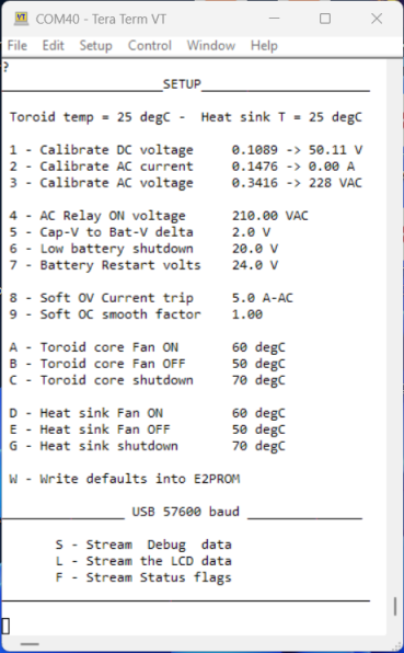 . Edited 2024-04-07 11:58 by KeepIS It's all too hard. Mike. |
||||
| KeepIS Guru Joined: 13/10/2014 Location: AustraliaPosts: 1399 |
Finally got around to knocking up an LCD on Veroboard to correctly test the LCD code. Found I had some of the LCD text incorrect, easy fix and now going great. Poida did a nice job with this, it's a very responsive almost real time display.  FYI there is no hookup wire underneath, and on the back, only two for the backlight control. 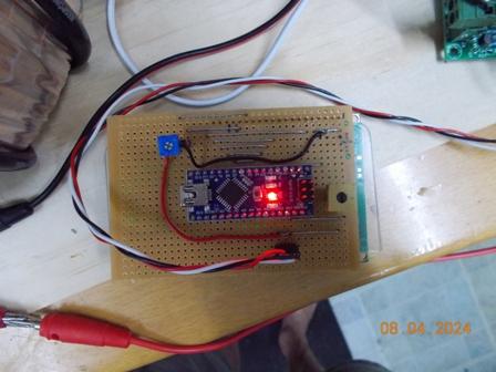 It's all too hard. Mike. |
||||
| KeepIS Guru Joined: 13/10/2014 Location: AustraliaPosts: 1399 |
I've been testing my code for my newly built Nano Controller after another complete rewrite, I'm also testing a new ATS, "Automatic Transfer Switch". The interface the Controller gives with the great hardware design by Wiseguy in the Nano Controller make this possible. The ability to accurately control the point of inverter AC changeover, and the simple interface method on the Controller board, allows me to bypass the Commercial ATS devices with their separate setup menus and associated problems. The new Controller allows me to use a simple robust Changeover Switch controlled by the Nano PCB. The amount of extra parts, power supply and wiring that this eliminates in the Inverter is amazing. The DC voltage set-points in the Nano controller are stable and very accurate. I can finely tune the Controller to handle the LiFePO4 bank correctly as voltage accuracy is a priority with such a small range of voltage change between 95% and 50% SOC. This new Controller does that. I have coded "15" different status messages for Battery to Controller monitoring and fault status. I employ a First Trip-Hold logical sequence to accurately display the exact reason for the failure to start, or reason to trip, this eliminates out of sequence false messages indications. Certain charge and trip conditions that could cause an unwanted fast shutdown restart cycle with the old style of inverter controllers has now been eliminated. The following shows the inverter running with the Toriod Fan on (tF) if the Heat-sink fan is on (hF) is displayed next to the tF fan position. I have tried to make use of the small amount of display real-estate available to display as much information as clearly as possible. So I'm happy with the result. The ability to watch the Capacitor bank charging with battery input at power on is something I really like - Kudos to Poida and his simple LCD streaming code. I know some of us here don't run our Toriods or Heat-sinks to the top of the nominal safe temperature Zones - so these setting shown will be reduced considerably - if my heatsink ever got to 40° it would mean I have a big problem as that heatsink is huge. I keep the toriod at around 50 deg max as it's around the max sweet spot and allows shorter fan time to hold it there. Yours will differ, I have 3 stacked cores, that's a lot of metal. I wanted the Menu system to look clean and easily readable. Calibration values do not need to be displayed - you can't change them manually - but it's nice to confirm them - so menu item [ J ] displays them below the menu for quick verification when needed. I hate having to change all values in the settings when I muck up the calibration during testing, so I have split the Inverter settings from the Calibration settings [ W and Z ], either can be restored without overwriting the other. Test Mode, as Wiseguy said, is a great way to test and fault find. The Menus will change when the Link is in test mode, and a few extra settings are available whilst others are hidden. The LCD indicates Test Mode as well. I have tried in vain to crash the inverter or trip it up - it's very impressive how well this little Nano works. ATS "Automatic Transfer Switch" 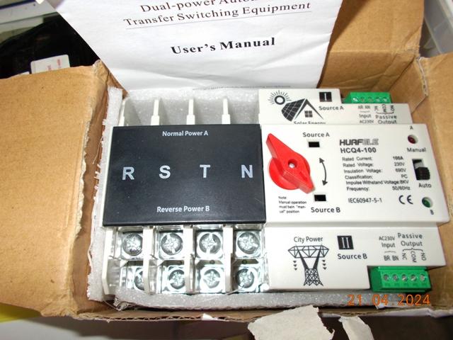   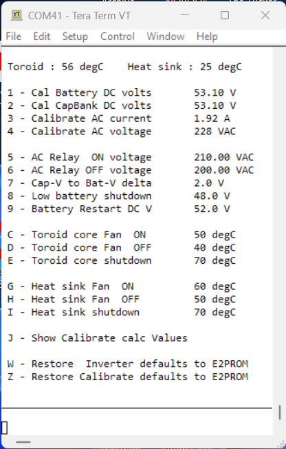 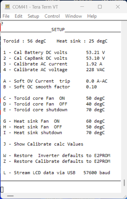 Edited 2024-04-21 20:40 by KeepIS It's all too hard. Mike. |
||||
| -dex- Regular Member Joined: 11/01/2024 Location: PolandPosts: 48 |
I have the exact same ATS switch. What is your grid power supply system? Does the N wire also get disconnected/switched? Does integration involve applying 230 voltage to the AR and AN ATS connectors from the nano "mains relay" control output? |
||||
