|

|
Forum Index : Microcontroller and PC projects : New 4 inch LCD
| Author | Message | ||||
palcal Guru Joined: 12/10/2011 Location: AustraliaPosts: 1873 |
I keep getting the error... ERROR IN MM.STARTUP I deleted MM.Startup and re wrote it but still the same. The first one works OK but when I try to calibrate I touch 2 targets and get the TOUCH HARDWARE FAILURE. The display works and calibrates ok on a Picomite. Although when I test touch, if I draw a line with the stylus the line does not appear where I touch and other pixels light up all over ther screen. However if I use the Text command to write something to the centre of the screen it appears in the correct place. Edited 2024-04-07 06:56 by palcal "It is better to be ignorant and ask a stupid question than to be plain Stupid and not ask at all" |
||||
| phil99 Guru Joined: 11/02/2018 Location: AustraliaPosts: 2135 |
That touch won't calibrate on any ILI9488 on that MM2 board, while I can't get it to fail (with the original ILI9488 driver) suggests it may be something to do with that board. Set up the display and a MM2 on a breadboard to see if that makes a difference. I will have a chance to test the new driver this afternoon. |
||||
palcal Guru Joined: 12/10/2011 Location: AustraliaPosts: 1873 |
Old breadboard had dodgy connections, I have a new one coming, will try it then. "It is better to be ignorant and ask a stupid question than to be plain Stupid and not ask at all" |
||||
| phil99 Guru Joined: 11/02/2018 Location: AustraliaPosts: 2135 |
Tested both new versions of the MM2 driver and touch calibrates ok with both. However the second one seems to require the 'invert' parameter, not optional. eg for non-inverting Sub MM.Startup Otherwise you get 'Error in MM.STARTUP' ILI9488 2, 23, 6, 1, 0 ' ILI9488 DCpin, RESETpin, CSpin, orientation [,invert] End Sub |
||||
| stanleyella Guru Joined: 25/06/2022 Location: United KingdomPosts: 2127 |
Hi phil. the isp ili9488 is the first display needing invert option afaik. got by fine without invert until this display. why invert after so long... and now it'll be a number? why ils needs inverting for the techno inquisitive please? |
||||
| phil99 Guru Joined: 11/02/2018 Location: AustraliaPosts: 2135 |
As far as I can tell the issue is the IPS (In-Plane Switching) panels use inverted logic compared to the standard TFT (Thin Film Transistor) type. The ILI9488 chip just passes whatever data it receives from the driver to the panel, so the driver needs to negate the negative to get positive colours. Only for the MM2 (PIC32MX170 chip). Peter will have the real answer but my guess is numbers are more efficient than words which is more important for the slower MX170 than the RP2040. Edited 2024-04-07 21:57 by phil99 |
||||
| Teo1 Newbie Joined: 06/05/2023 Location: RomaniaPosts: 25 |
Hi matherp , Do you have any datasheet and an example of use for display shown by you ? Thanks in advance , Teo |
||||
| OA47 Guru Joined: 11/04/2012 Location: AustraliaPosts: 926 |
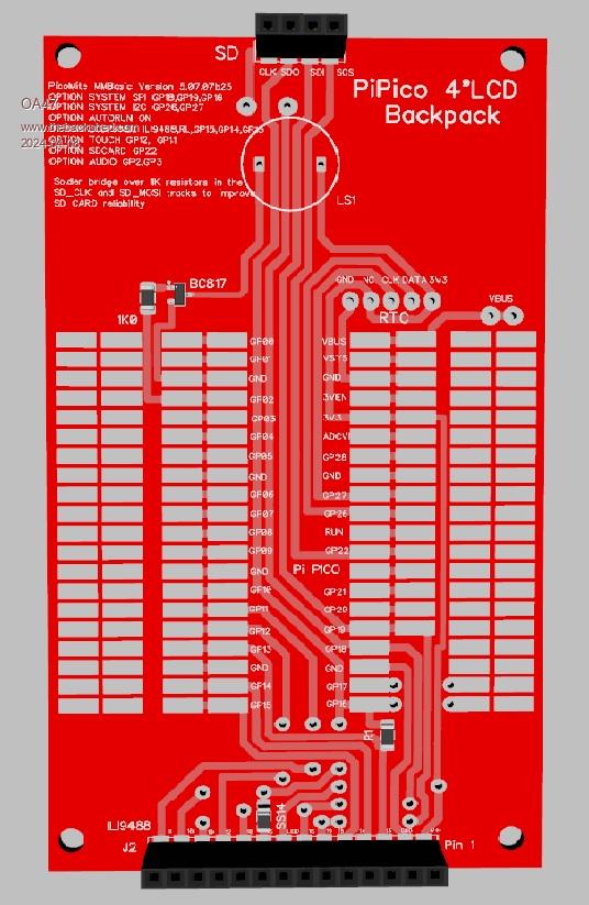
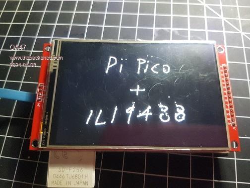
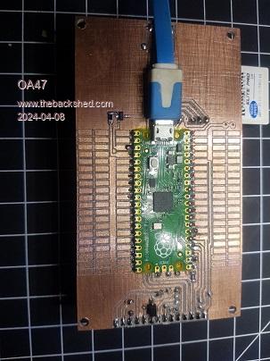
Not sure if any shedders may have a use for it but here's a ILI9488 4inch experimenters backpack. It has screen, touch, sound, RTC and SD access. I used Capton tape on the back of the pico and soldered it directly to the board but you could drill to mount it on pins.    I can upload the gerbers if anyone is interested. 0A47 Edited 2024-04-09 07:20 by OA47 |
||||
| phil99 Guru Joined: 11/02/2018 Location: AustraliaPosts: 2135 |
@Palcal, the plot thickens. Just got a 4" IPS ILI9488 (same blotch on the screen, same cure - thanks) and GUI CALIBRATE works perfectly on a MM2, verified with Gui Test Touch, But won't calibrate on a Pico (PicoMite MMBasic Version 5.09.00RC3). Copying the calibration from the MM2 to the Pico doesn't help - Gui Test Touch does nothing. Footnote added 2024-04-09 15:49 by phil99 x=touch(x) : y=touch(y) :? x,y Always returns -1, -1 if executed while being touched on the Pico but returns the correct values on the MM2. |
||||
palcal Guru Joined: 12/10/2011 Location: AustraliaPosts: 1873 |
I copied the calibration values with the same result. "It is better to be ignorant and ask a stupid question than to be plain Stupid and not ask at all" |
||||
| matherp Guru Joined: 11/12/2012 Location: United KingdomPosts: 9114 |
Bit difficult to follow but are you saying that touch isn't working on the IPS ILI9488 but is on the standard ILI9488 in the same circuit? If this is the case please try the attached and let me know if it improves anything PicoMite.zip |
||||
| morgs67 Regular Member Joined: 10/07/2019 Location: AustraliaPosts: 75 |
@phil99 The IPS 4" screen I have works fine on the picomite. Calibrated OK a couple of times. Touch test also working ok. The display is modified with the diode and resistor along with the miso pin cut off. Not using sdcard connections. Tony |
||||
| phil99 Guru Joined: 11/02/2018 Location: AustraliaPosts: 2135 |
Hi Peter, thanks for looking at it. The new .uf2 also gives "Error : Touch hardware failure" with GUI Calibrate. It's a puzzle, 2 3.5" ILI8488s work fine on both the Pico and the MM2. Palcal and morgs67 have the 4" IPS touch working on the Pico. Palcal can't get touch to work on the MM2 while my IPS works on the MM2 but not the Pico. Does Not Compute! |
||||
| morgs67 Regular Member Joined: 10/07/2019 Location: AustraliaPosts: 75 |
@0A47 Like the look of your experimenters backpack. Would it be possible to place holes in all the pads so that pins/sockets could be used as well for all connections. also if you added another set of holes that matched the sd card connectors on a 3.5" both displays could be accommodated. Tony |
||||
| OA47 Guru Joined: 11/04/2012 Location: AustraliaPosts: 926 |
Good thoughts Tony, I could add those holes if I were to get the boards made but as shown I was minimalizing any errors I could produce on the prototype boards I have milled, drilled and cutout on the CNC. BTW Do you have a measurement for the spacing between the pins for the 3.5 inch version ? 0A47 |
||||
| phil99 Guru Joined: 11/02/2018 Location: AustraliaPosts: 2135 |
My IPS touch issue on the Pico is fixed. Contact cleaner in the socket did the trick. Somehow the old panels made contact but T_CLK pin on the new one didn't. Palcal, probing all the Panel pins to the Pico found it so perhaps that is worth doing on your MM2. |
||||
| OA47 Guru Joined: 11/04/2012 Location: AustraliaPosts: 926 |
If the link from BL to 3V3 is re-directed to the hole on GP17 and the OPTION LCDPANEL changed the Backlight 0-100% works a treat.  0A47 |
||||
palcal Guru Joined: 12/10/2011 Location: AustraliaPosts: 1873 |
I checked all continuity pin to pin. I've gone round in circles so many times I'm losing track. Does calibrating the display do anything to the display itself. "It is better to be ignorant and ask a stupid question than to be plain Stupid and not ask at all" |
||||
palcal Guru Joined: 12/10/2011 Location: AustraliaPosts: 1873 |
I didn't realise that on some panels the LED is marked BL. I assume that the BL pin is connected to a PWM pin. Is it OK to use the mosfet circuit as on the Micromite Backpack with these panels as it supplies 5v. Are the panels marked BL only 3.3v. The first 4" panel I was playing with now has a dead backlight. Edited 2024-04-10 07:25 by palcal "It is better to be ignorant and ask a stupid question than to be plain Stupid and not ask at all" |
||||
| OA47 Guru Joined: 11/04/2012 Location: AustraliaPosts: 926 |
Palcal, when I traced the BL connection on the 4 inch ILI9488, it seemed to go to a single transistor circuit that converts the 3V3 PWM to a variable voltage for the backlight led. I would expect if you have been supplying 5v PWM to the transistor circuit the display would have not had a smooth backlight variation and you may have hurt the transistor circuit. You may be able to retrieve the backlight operation by linking the BL pin on the display to the other side (display side) of the transistor circuit with a resistor. 0A47 |
||||