|

|
Forum Index : Microcontroller and PC projects : PicoMite: driving a small speaker
| Author | Message | ||||
| Mixtel90 Guru Joined: 05/10/2019 Location: United KingdomPosts: 6812 |
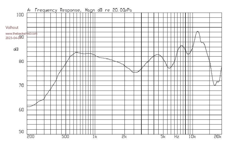
That may be overkill if the original speaker is mounted on a baffle (i.e. stuck to the case with hot glue). It doesn't have a great response, but once you get above 400Hz-500Hz it has useful output. You won't hear it without a baffle though. At the end of the day this is a handheld game. There's no room for a "good" speaker. The answer is to get the best out of a little one by mounting it properly and not feeding it stuff that it can't reproduce. It's no good giving it 100Hz or, in fact, anything below 400Hz at all. Putting two speakers in parallel (4R load rather than 8R if the amp can handle it) (in phase) will allow a bit more power handling and will vibrate more of the box, making it louder. It's not stereo but does that matter? Mick Zilog Inside! nascom.info for Nascom & Gemini Preliminary MMBasic docs & my PCB designs |
||||
| hitsware2 Guru Joined: 03/08/2019 Location: United StatesPosts: 713 |
I didn't understand the " handheld " part . > It's not stereo but does that matter? Not as a rule . my site |
||||
| phil99 Guru Joined: 11/02/2018 Location: AustraliaPosts: 2140 |
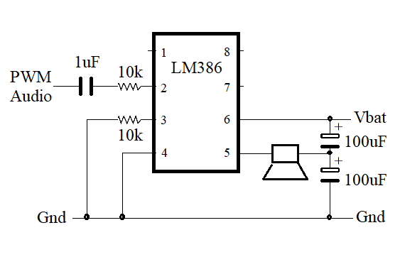
Hi Tom, Apologies, I left out some resistors that didn't seem to make much difference at 5V but are needed at anything less. The inductor resistance is too high so omit it and the 100nF across the speaker. With b33 - OPTION CPUSPEED 378000 for 132.3kHz PWM frequency the voice coil inductance may be enough. Play TONE 999,999 POKE SHORT &h40050000,&h09 'change to suit your PWM channel chip 1 PWM L to 10k to pin 3 Gnd to 10k to pin 2 Vbat to pin 6 Gnd to pin 4 Speaker+ to pin 5 chip 2 PWM R to 10k to pin 3 Gnd to 10k to pin 2 Vbat to pin 6 Gnd to pin 4 Speaker- to pin 5 To ensure the phase shift is happening measure the AC voltage between L & R Pico pins. It should be about 2V. If your meter can read up to 132kHz, one of mine only goes to 20kHz. As I only have one chip the speaker is going to ground via a 220uF cap. and is moderately loud. A baffle really makes a difference. Edit. Further testing. A capacitor in series with the input reduces distortion. With a single chip noise is reduced a little if the speaker goes to the junction of two capacitors connected between V+ and Gnd. Might help with other amplifiers too.  Component values not critical. Pins 2 & 3 are inverting and non-inverting inputs so for bridged output the POKE trick isn't needed, just swap pins 2 & 3 on the second chip. As the PWM phase of L & R are the same both inputs could go to the same pico pin. chip 1 PWM L to 1uF to 10k to pin 3 Gnd to 10k to pin 2 Vbat to pin 6 Gnd to pin 4 Speaker+ to pin 5 chip 2 PWM R to 1uF to 10k to pin 2 Gnd to 10k to pin 3 Vbat to pin 6 Gnd to pin 4 Speaker- to pin 5 Edited 2023-04-03 13:46 by phil99 |
||||
| Mixtel90 Guru Joined: 05/10/2019 Location: United KingdomPosts: 6812 |
See the third post in this thread. Squeezing a 2" speaker in would be a work of art and may even require TARDIS technology. :) Mick Zilog Inside! nascom.info for Nascom & Gemini Preliminary MMBasic docs & my PCB designs |
||||
| Volhout Guru Joined: 05/03/2018 Location: NetherlandsPosts: 4253 |
@phil99 You are aware you are immensly overdriving the LM386 input ? Maybe this is allowed (the input transistor may act as a diode clamp) but it feels dangerous. Regards, Volhout PicomiteVGA PETSCII ROBOTS |
||||
| phil99 Guru Joined: 11/02/2018 Location: AustraliaPosts: 2140 |
Yes, deliberately overdriving it to prevent linear operation. The idea is to clip the input to remove much of the noise and ensure maximum p-p PWM output. Previously I was overdriving it too much but now the LM386 chip I have sounds good with a small speaker. |
||||
| Volhout Guru Joined: 05/03/2018 Location: NetherlandsPosts: 4253 |
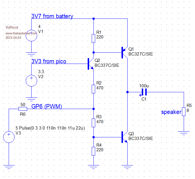
@phil, @mozzie, In case you are looking for a half-bridge with discrete components, my simulation say this would work. The speaker might need a low pass filter (an inductor, maybe capacitor) and a volume potmeter. But this power stage will give you rail-to-rail output with a 3.7V...4.2V battery voltage, and because isolates the 3.3V switchmode ripple, will give you a clean output (as long as the battery voltage is clean). Q1 and Q3 need to be medium power transistors with relatively high gain, such as the BC327/BC337. Q2 can be a standard BC547/BC548 or alike. Resistor values must be as indicated (R3/R2 = 2 x R4/R1) to minimize crossover (current peaks from battery).  Edited 2023-04-03 18:30 by Volhout PicomiteVGA PETSCII ROBOTS |
||||
| phil99 Guru Joined: 11/02/2018 Location: AustraliaPosts: 2140 |
The main reason for using the LM386 is Tom has them. Second reason is simplicity. Yes an output filter would be nice but the inductors Tom has have too much resistance. Upping the PWM frequency to 132.3kHz reduced the idle PWM current through my speaker to about 30mA without any extra inductance. |
||||
| thwill Guru Joined: 16/09/2019 Location: United KingdomPosts: 4047 |
Hi folks, I'm taking a breather from actually "doing anything" to update my logbook and accumulate some parts, but that doesn't mean I don't have follow up questions: @phil99: What inductor are you recommending for the "LM386 circuit" ? @Volhout: I like the discrete parts only "transistor circuit", what's the "5 Pulse" malarkey on the V3/signal-source ? I'm guessing it is the input to some sort of circuit simulator package ? @Volhout: In your "diode clipper circuit" - Do I still want a 2.2uF cap between the volume/pot and the PAM8403 input, I noticed I have one "left over" on my breadboard from a previous iteration ? - Likewise the 2.2R in series on the PAM8403 VDD ? What is/was that for by the way, to my ignorant mind 2.2R is just a bad piece of wire ;-) Best wishes, Tom Game*Mite, CMM2 Welcome Tape, Creaky old text adventures |
||||
| phil99 Guru Joined: 11/02/2018 Location: AustraliaPosts: 2140 |
" What inductor are you recommending for the "LM386 circuit" ?" For testing purposes just leave it out. The voice coil inductance of mine was enough with the PWM frequency at 132.3kHz - beta 33 CPU speed 378MHz. If the no signal PWM AC current through the speaker is less than say 50mA then that will do. If you do add one its DC resistance needs to be much lower than the speaker resistance as it will be reducing the volume. 100uH to 470uH should be enough. |
||||
| Volhout Guru Joined: 05/03/2018 Location: NetherlandsPosts: 4253 |
1/ The circles at the left side of the schematics are simulator models of battery(4V), switchmode power supply(3V3) and PWM output (44kHz). These are just wires you connect to the succesive circuits. 2/ My PAM8403 module has a potmeter and capacitor between potmeter and PAM8403 chip. This makes me believe you need a capacitor between potmeter and PAM8403 chip. 3/ In my bench test I did not have a 2.2R resitor between PAM8403 board and battery. Thus I cannot decide if improves. My circuit has a capacitor between Vdd and GND on the PAM, and I hard wired it to the battery (no resistor, not filter, not extra electrolytic capacitors, just wires to supply power). Volhout PicomiteVGA PETSCII ROBOTS |
||||
| mozzie Regular Member Joined: 15/06/2020 Location: AustraliaPosts: 68 |
G'day All, Not sure if Peter is going to chime in here and update but he has changed the functionality of the play sound command and solved the noise problem completely when using analog amps and filters for mono sound.  By using "M" Mono in the play sound command it inverts the R channel, not logical invert but signal inversion, so now the outputs are differential, this is great news. I have tested a very simple circuit with a PAM8302 mono amp with differential inputs and it is quiet as the grave with no signal even with a simple single stage filter and very little supply bypassing. This is with USB / battery on VSYS or from the 3V3 supply. Also has very low quiesient current (7mA) compared to class "D" switching solutions, although this is now far easier also.  Those LM386's in analog bridge mode might be the solution after all (or a TDA2822 / LM4871) Once again, my thanks to Peter.  @Volhout That circuit looks interesting, I might give it a try to see how it goes. Regards, Lyle. |
||||
| matherp Guru Joined: 11/12/2012 Location: United KingdomPosts: 9139 |
Remember - only works in PLAY SOUND, not PLAY WAV or PLAY TONE or PLAY FLAC coming soon |
||||
| Volhout Guru Joined: 05/03/2018 Location: NetherlandsPosts: 4253 |
I didn't think of that, but you are right. The noise is more audible when silent, and when both PWM channels have the same noise it cancels out in differential mode. And when drive to the extremes, one channel will have zero (ground) noise, the other will have maximum noise. But on top of the loud signal, you won't hear it.... smart thinking. You only should NOT use the single volume potmeter on the PAM8302 board, since it only attenuates one input. Then you will start hearing the noise again. So the low pass filter for both outputs whould have identical attenuation buid in (or a stereo potmeter for a mono channel). Volhout PicomiteVGA PETSCII ROBOTS |
||||
| mozzie Regular Member Joined: 15/06/2020 Location: AustraliaPosts: 68 |
Cheers Peter, WAV files we can invert during conversion, Play Tone would be handy (maybe -XXX for invert) but I'm not pushing my luck  Play FLAC sounds interesting Play FLAC sounds interesting  Volhout, the PAM8302 has a fully differential input stage with the pot wired across them, I can find no earth reference at all with a meter. The software volume control is probably a better solution (pot into ADC)  Have now tried the same circuit with a TDA2822M (search and ye shall find), this is also very quiet with the noise from the PSU on Battery supply just audible (worst mode) and with the volume wound up way too far, amp well into clipping when playing. Hopefully this is the cure for the TomBoy system. Regards, Lyle. |
||||
| hitsware2 Guru Joined: 03/08/2019 Location: United StatesPosts: 713 |
A lot simpler than tda2822 .... Just pad down the input for gain control ...... my site |
||||
| Volhout Guru Joined: 05/03/2018 Location: NetherlandsPosts: 4253 |
Not sure, the datasheet doe not identify the second input as an inverting input. Could work, or not... Volhout PicomiteVGA PETSCII ROBOTS |
||||
| Volhout Guru Joined: 05/03/2018 Location: NetherlandsPosts: 4253 |
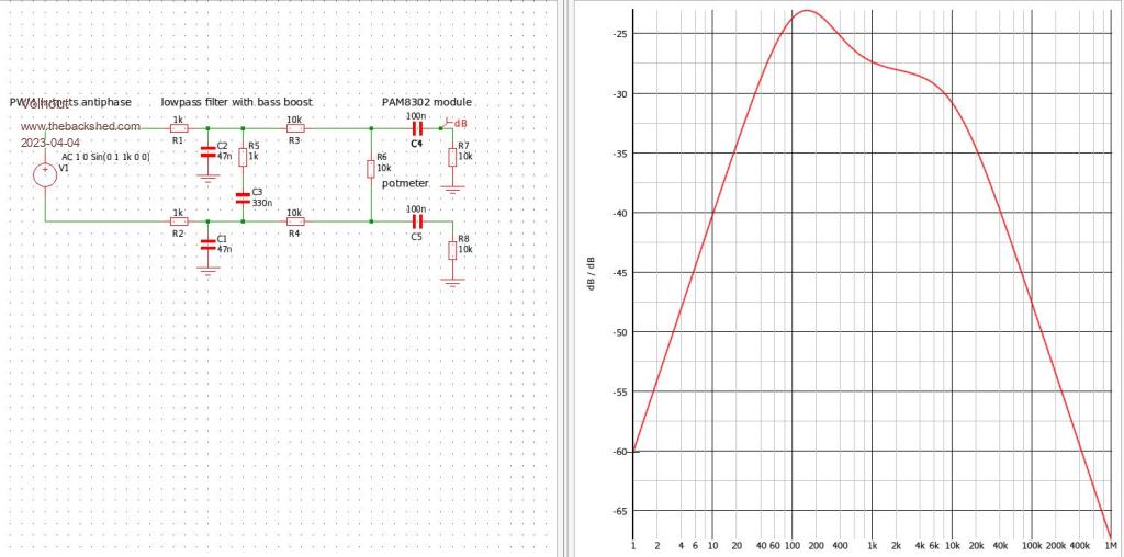
@mozzie, The small speakers Tom has, have terrible low frequency behaviour.  But since the PAM8302 can drive enough power, we could boost the rolloff a bit. Below is an example how this can be done. This is by no means perfect, but the 2 components (R5,C3) boost some 5 db. The maximum is -23dB (@100Hz), with 24dB gain, the PAM8302 will bring this back to 0dB (2.8V accross the 8 ohm speaker = 0.6 watt).  Volhout Edited 2023-04-04 06:04 by Volhout PicomiteVGA PETSCII ROBOTS |
||||
| thwill Guru Joined: 16/09/2019 Location: United KingdomPosts: 4047 |
Hi folks, Forewarning that I have ordered some alternative speakers to try out https://www.aliexpress.com/item/1005004442963049.html. They are made of finest Chinesium and I don't have a spec sheet  . .Also am I to understand that the PAM8403 design is falling out of favour (not that it was ever particularly in favour with anyone but me and Bill) and that I might expect some recommendation based on magic recently implemented by Peter, which I don't understand. Don't two waves in anti-phase cancel each other out ? Best wishes, Tom Game*Mite, CMM2 Welcome Tape, Creaky old text adventures |
||||
| Turbo46 Guru Joined: 24/12/2017 Location: AustraliaPosts: 1611 |
Tom, there are some specs on that page further down. Frequency range 500-5000Hz. Please see this site regarding a warning on cancer causing materials https://www.ebay.com/itm/314253688215 Any device you choose that gives results that are acceptable to you is fine by me but if you would like others to build it with components that are sourced from who knows where, then you really should use them within their quoted specs. You mentioned that you might try raising the music up one octave. That may be better than expecting magic from a tiny speaker. Bill Keep safe. Live long and prosper. |
||||