
|

|
Forum Index : Microcontroller and PC projects : RP2350 firmware
| Author | Message | ||||
| homa Guru Joined: 05/11/2021 Location: GermanyPosts: 351 |
Peter this is version b2. I tried that one. But I'm happy to wait for b3 and look forward to 320x240x32768 color modes. I am very interested. Are you also planning a 16:9 mode or all just 4:3 modes? Matthias |
||||
| matherp Guru Joined: 11/12/2012 Location: United KingdomPosts: 9110 |
Can't do anything in 16:9 as the bus bandwidth isn't high enough. It is possible to clock out static data from RAM but as soon as you start to change the data the picture breaks up. Unlike the STM32H7 the CPU speed is directly tied to the DVI speed by a simple divider so for HDMI I'm running the CPU at 315MHz and the DVI at 157.5MHz. Any different format requires the CPU to be clocked at a different speed and it all gets too clunky. |
||||
| homa Guru Joined: 05/11/2021 Location: GermanyPosts: 351 |
Ah, would you like to explain that in more detail? I thought it was more about memory consumption. That's why I was thinking of a low resolution like QHD (Quarter HD) 640×360, 16∶9. In theory, I know that the image generation is related to the clock, but not exactly how. Therefore, I cannot classify the 157.5MHz in this context. |
||||
| matherp Guru Joined: 11/12/2012 Location: United KingdomPosts: 9110 |
Pixel rate is 31.5MHz. DVI sends 10 bits per pixel using both edges of the clock so this takes 5 clock cycles. Therefore 5 * 31.5 = 157.5 |
||||
| matherp Guru Joined: 11/12/2012 Location: United KingdomPosts: 9110 |
V6.00.00b3 PicoMiteRP2350.zip Fixes the WS2812 bug Lots of work on the video output. NB: For both VGA and HDMI versions 320x240*16 bits of memory are allocated for video memory. In all cases the screen will see a 640x480 image with a refresh rate of 75Hz (31.5MHz pixel rate) Video Modes VGA and HDMI Mode 1: 640x480x2bits with tiles. Tiles width is fixed at 8 pixels. Tile height defaults to 12 pixels but can be from 8 to MM.HRES. Tiles colours are specified using the standard RGB888 notation. This is converted to RGB121 for VGA versions and RGB555 for HDMI versions. A framebuffer (F) and a layer buffer (L) can be created. These have no impact on the display and do not use user memory but both can be used for creating images and copying to the display screen (N) Mode 2: 320x240x4 bits. A framebuffer (F) can be created. This have no impact on the display and does not use user memory but can be used for creating images and copying to the display screen (N). In addition a layer buffer can be created. This also does not use user memory. any pixels written to the layer buffer will automatically appear on the display sitting on top of whatever may be in the main display buffer. A colour can be specified (0-15: defaults to 0) which does not show allowing the main display buffer to show through. Map functionality is available to override the default colours of the 16 available In the case of VGA, the hardware is limited to the 16 colours defined by the resistor network. In the case of HDMI each of the 16 colours can be mapped to any RGB555 colour. Use MAP GREYSCALE to have 16 shades of grey from black to white available. mode 2 framebuffer layer framebuffer write l text 160,120,"hello",cm,,5,rgb(red) framebuffer write n gui test lcdpanel Mode 3: 640x3200x4 bits. A framebuffer (F) can be created. This have no impact on the display but uses a big chunk of user memory. It can be used for creating images and copying to the display screen (N). In addition a layer buffer can be created. This also uses a big chunk of user memory. Any pixels written to the layer buffer will automatically appear on the display sitting on top of whatever may be in the main display buffer. A colour can be specified (0-15: defaults to 0) which does not show allowing the main display buffer to show through. The RP2350 memory can only hold one of a layer buffer and a framebuffer unless PSRAM is available. If PSRAM is available the layer buffer must be created first as it must be in the processors tightly coupled memory. Map functionality is available to override the default colours of the 16 available In the case of VGA, the hardware is limited to the 16 colours defined by the resistor network. In the case of HDMI each of the 16 colours can be mapped to any RGB555 colour. Use MAP GREYSCALE to have 16 shades of grey from black to white available. Additional HDMI Video Modes Mode 4: 320x240x16 bits This is full RGB555 allowing good quality colour images to be displayed A framebuffer (F) and a layer buffer (L) can be created. These have no impact on the display and use big chunks of user memory but both can be used for creating images and copying to the display screen (N). Only one can be created unless PSRAM is available. Mode 5: 320x240x8 bits A framebuffer (F) can be created. This have no impact on the display but uses a big chunk of user memory. It can be used for creating images and copying to the display screen (N). In addition a layer buffer can be created. This does not use user memory. Any pixels written to the layer buffer will automatically appear on the display sitting on top of whatever may be in the main display buffer. A colour can be specified (0-255: defaults to 0) which does not show allowing the main display buffer to show through. Map functionality is available to override the default colours of the 256 available Each of the 256 colours can be mapped to any RGB555 colour. Use MAP GREYSCALE to have 32 shades of each of the 7 standard colours conveniently available. MAP(0) to MAP(31) - grey, MAP(32) to MAP(63) - blue etc. Have a play. MODE 5 Map greyscale j=(320-256)/2 For i=0 To 255 Line i+j,0,i+j,MM.VRes-1,1,Map(i) Next 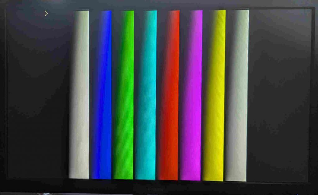 Edited 2024-09-02 03:43 by matherp |
||||
| Mixtel90 Guru Joined: 05/10/2019 Location: United KingdomPosts: 6781 |
Wow.... you *have* been busy! :) Great work, as usual. Thanks! Mick Zilog Inside! nascom.info for Nascom & Gemini Preliminary MMBasic docs & my PCB designs |
||||
| stanleyella Guru Joined: 25/06/2022 Location: United KingdomPosts: 2120 |
Peter ,if I may call you that, amazing ,impressive hdmi/dvi for the less brighter colours in palette I remembered I added a graphic card and it had a dvi connector and it's in a 22" monitor. the card was for open gl for 3d printer but was waste of money. I can get an hdmi breakout plug... similar to vga breakout plug I got or should I not bother with the video developments until the dust settles. there's assembler posts now. was in the '80's |
||||
| homa Guru Joined: 05/11/2021 Location: GermanyPosts: 351 |
Peter thank you. I have just tried to transfer files via xmodem. USB Edition 6.00.00b3 and GP8/9 uart. Unfortunately it fails, does anyone else have this problem? |
||||
| matherp Guru Joined: 11/12/2012 Location: United KingdomPosts: 9110 |
Stan Given that you are a breadboard expert why not buy a HDMI breakout. I use the Adafruit one e.g. I wouldn't buy the ones with screw connectors as they are very clunky but the Adafruit one has the needed resistors built in so is a doddle to wire Edited 2024-09-02 04:31 by matherp |
||||
| stanleyella Guru Joined: 25/06/2022 Location: United KingdomPosts: 2120 |
not breakout just make it vero. no, just cad a pcb, er not really. the pico2 graphics look interesting so suggested hdmi board will not be redundant before it arrives as everything is so dynamic and ephemeral... why I don't use pcb. I should get more pico2... or not ok.what's needed is an explanation of pico2 "hdmi" ie will it work with a 14" tv. I know it's all new but looks interesting and want to get involved with 640x480 coloured pixels...not spectrum chr attributes the other pico2 is driving ili9341 fine, boring, nothing to moan about :) works same as 2040, sd, touch, bubble universe Edited 2024-09-02 06:22 by stanleyella |
||||
| JanVolk Senior Member Joined: 28/01/2023 Location: NetherlandsPosts: 144 |
https://learn.adafruit.com/adafruit-dvi-sock-for-pico/overview And this fits nicely on the new Raspberry Pi Pico 2 board and together on a breadboard. Jan |
||||
| Mixtel90 Guru Joined: 05/10/2019 Location: United KingdomPosts: 6781 |
Peter's suggestion is a good one, Stan. You only need to put a socket strip on the stripboard and it'll plug straight in when you want it. Or it'll plug straight into breadboard. Mick Zilog Inside! nascom.info for Nascom & Gemini Preliminary MMBasic docs & my PCB designs |
||||
| Mixtel90 Guru Joined: 05/10/2019 Location: United KingdomPosts: 6781 |
WS2812B is working, but red and green are reversed. This is a 5mm packaged one rather than a surface mount. I'll try one of those tomorrow. It's the same whether I set it to B, O or S type. Mick Zilog Inside! nascom.info for Nascom & Gemini Preliminary MMBasic docs & my PCB designs |
||||
| Bleep Guru Joined: 09/01/2022 Location: United KingdomPosts: 509 |
Does anyone know if there is a way of connecting the HDMI to a Display Port monitor, it appears that an active converter is required, unless anyone knows of a way? Thanks. |
||||
| stanleyella Guru Joined: 25/06/2022 Location: United KingdomPosts: 2120 |
https://coolcomponents.co.uk/products/dvi-breakout-board-for-hdmi-source-devices looks very complicated... for normal people :) show us a picture of it wired please. is it easy to wire/software and hdmi tv happy days? |
||||
| Mixtel90 Guru Joined: 05/10/2019 Location: United KingdomPosts: 6781 |
Forget that about the WS2812B. A proper one is working fine. The problem is with these oddball ones. It doesn't matter as long as you know what the problem with them is. :) Stan: I have to admit that board is confusing. The silkscreen doesn't tie in with the list of connections that they give you! There are 8 connections plus ground. The connections are in pairs: D0+ and D0-, D1+ and D1-, D2+ and D2-, CK+ and CK-. Each D pair carries a digital stream for a colour. The CK pair carry the clock signal. They are in pairs because they run at high speed so simple red, green and blue couldn't handle it. There's a lot more information than you have with VGA. From this point of view it's no worse to connect up than VGA - just a couple of extra pins. All the signals have a current limiting resistor of around 220R-270R. The breakout modules almost all have them mounted on the module so you don't need to bother about them. It looks like this to me: GP12 - 0+ GP13 - 0- GP14 - TXC+ GP15 - TC- GP16 - TX2+ GP17 - TX2- GP18 - 1+ GP19 - 1- Then the GND pins (you'll probably get away with just one) Pimorini site has a breadboard pic Mick Zilog Inside! nascom.info for Nascom & Gemini Preliminary MMBasic docs & my PCB designs |
||||
| Sasquatch Guru Joined: 08/05/2020 Location: United StatesPosts: 362 |
Here is the obligatory Mandelbrot in Mode 4. RP2350 HDMI 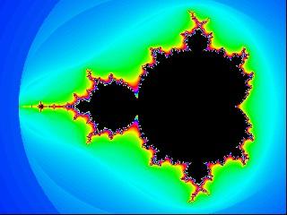 -Carl |
||||
| Volhout Guru Joined: 05/03/2018 Location: NetherlandsPosts: 4223 |
A typo, I assume.... PicomiteVGA PETSCII ROBOTS |
||||
| homa Guru Joined: 05/11/2021 Location: GermanyPosts: 351 |
Hi Peter, there is still a small bug with the MAP test program. If it is run in mode 3 (works) and then aborted with Ctrl+C, the system colors are no longer correct. Especially in the editor. 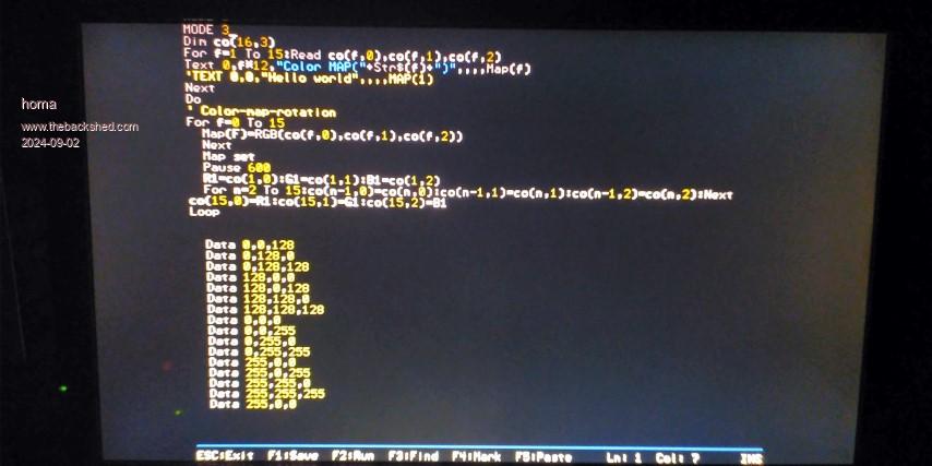 On the other hand it works fine in mode 1 and 5 and the system colors are restored there as well. 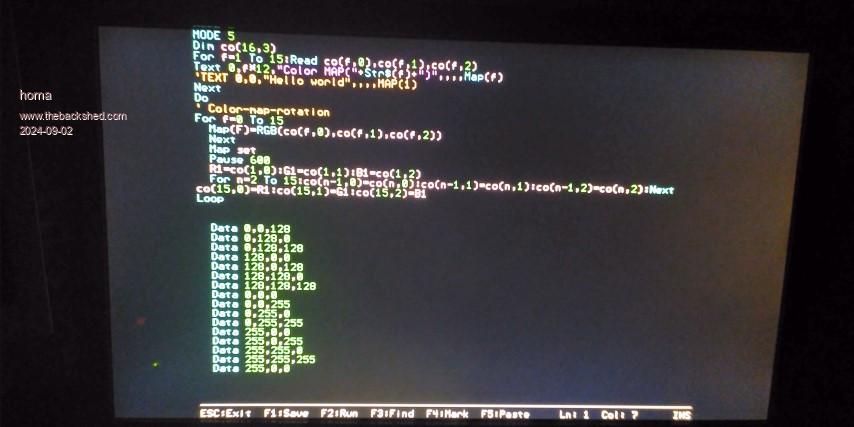 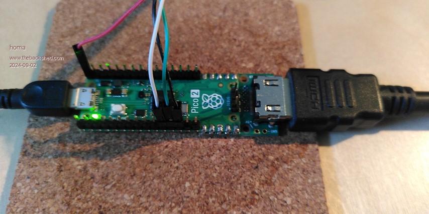 Anyone else having problems with XMODEM? I cannot send files to the Pico2 (b3). The transfer starts and then freezes ... it works in the other direction. Matthias Edited 2024-09-02 19:59 by homa |
||||
| matherp Guru Joined: 11/12/2012 Location: United KingdomPosts: 9110 |
This one is a no-win. If I reset the colour palette after ctrl-C then it is a pain when testing a program that uses it. If I don't then you get the effect you see. Use MAP RESET to reset the colours before entering the editor in mode 3. In modes 2 ,4, and 5 the editor automatically switches to mode 1 for editing to get the 640x480 resolution but this is then restricted to font 1 to match the tile size in order to get colour coding Mode 3 is already 640x480x16colour and therefore colour coding is available with any font. A compromise would be to just reset the palettes when entering the editor but leave them after ctrl-C at the command line leaving it up to the user to issue the MAP RESET if they wish |
||||