
|

|
Forum Index : Microcontroller and PC projects : Colour Maximite 1.5? or something
| Author | Message | ||||
Grogster Admin Group Joined: 31/12/2012 Location: New ZealandPosts: 9307 |
I hate github.  As there is no ZIP or otherwise full-package of all the files to download, I tried to download them one by one to a folder on my PC - right-click the file, click 'Save linked content as...', and save. That worked for all files, but they are all corrupted. CLICK on the likes of the schematic PDF, that then opens in another window inside github, and I can download it from there, but this is the kind of crap that makes me hate github so much. Rant, rant, rant..... Smoke makes things work. When the smoke gets out, it stops! |
||||
| Turbo46 Guru Joined: 24/12/2017 Location: AustraliaPosts: 1611 |
Hi Grogster, If you go the the Github page and click on the green "<> Code" button and then "Download ZIP" you can get the whole package. I looks OK to me. Bill Keep safe. Live long and prosper. |
||||
Grogster Admin Group Joined: 31/12/2012 Location: New ZealandPosts: 9307 |
Obviously, I was not driving github correctly.  I've ordered five to play with. Cost came out as US$125.47 including DHL delivery, so that breaks down as US$25.09 per unit, and I absolutely ADORE that Peter has put the connectors etc, on the BOM/CPL, so that the boards basically come back FULLY assembled - no need for me to add the through-hole connectors myself etc, which all takes time, so this is lovely.   I have a USB A-A cable for doing the CMM2 programming, so it should be dead-easy to do these new boards. I look forward to trying them out! I only got five, in case Peter suddenly needs to change something on the design - PCB prototyping can be like that.   Once we are all happy that things are good and no more MAJOR changes are needed, I can order larger batches of boards, and I will put them up on my website. Smoke makes things work. When the smoke gets out, it stops! |
||||
| Mixtel90 Guru Joined: 05/10/2019 Location: United KingdomPosts: 6787 |
I suspect that those who have ordered one from Peter may not have to wait too long now. Mine has just turned up, but I'm also in the UK so it's usually pretty quick post to where I am. Peter supplied it with MMBasic preinstalled, so it was quite literally plug & play, although you'll need to fit a CR2032 and, if you want to connect speakers, you'll need a jumper for the amp supply header (I've not tested this yet). It worked first time - just plug in a USB keyboard then power up via a USB-C cable from your PC. My only moan so far is that the positioning of the volume control makes it difficult to fit it into any sort of a case. If you have access to a 3D printer then Peter's design will be the best you can manage, I think. However, I'm pressing on with my ABS and acrylic design now that I've got the materials. Mick Zilog Inside! nascom.info for Nascom & Gemini Preliminary MMBasic docs & my PCB designs |
||||
| lizby Guru Joined: 17/05/2016 Location: United StatesPosts: 3150 |
For my order, the 2x20 connecters were marked "out of stock"--glad for others that they are available now. If I can find them, I should have some of the shrouded right angle male headers somewhere. PicoMite, Armmite F4, SensorKits, MMBasic Hardware, Games, etc. on fruitoftheshed |
||||
| Bleep Guru Joined: 09/01/2022 Location: United KingdomPosts: 509 |
Hi Peter, The board has arrived safely thanks. I am however completely failing to get the serial console working. I have enabled COM 2 with :- Option Serial Console Com2,GP8,GP9 Which has been accepted and is listed in the Options list, however when I connect a USB cable (A-C) to my laptop, I see a USB0 Port appear, but it immediately disappears and I am unable to connect over serial, I have also tried connecting to a PC and I do get a COM3 port, but again I can't seem to connect to it, I get "USB-SERIAL CH340 (COM3)" in Devices, the port reports 9600, Data bits 8, parity None, stop bits 1, flow control none. I am using PuTTY, any ideas as to what I'm doing wrong? I have now been able to check out the circuit, GP8 & 9 are connected to Pins 2 & 3 of the CH340C, similarly, checked the USB data lines all the way from Pins 5 & 6 all the way to the end of a USB cable, all resistors R31,32,33 are present and correct, R33 is 1M, but drops to 0 Ohm when a USB C plug is inserted, which I'm assuming is correct? As a sanity test I have installed the non USB version and have been able to connect to the console, using the USB A plug, I have also installed your very latest B1, so I currently have no ideas? Regards Kevin. |
||||
| matherp Guru Joined: 11/12/2012 Location: United KingdomPosts: 9115 |
Kevin The board was correctly configured and tested when posted and should have worked out of the box. If possible try with teraterm on windows. The serial port is set to 115200. MAKE SURE THE TERMINAL PROGRAM IS SET TO 115200. It tells the CH340 what baudrate to use on the TTL side over the USB descriptor. This is not the same as a CDC port where the baudrate setting doesn't matter Start by re-loading the USBVGA firmware and then do OPTION RESET. The console should then be working with no other options set. Then apply the options as listed. NB: OPTION VGA PINS must be done before OPTION AUDIO Edited 2024-02-16 03:37 by matherp |
||||
| Bleep Guru Joined: 09/01/2022 Location: United KingdomPosts: 509 |
Hi Peter, Current Options. 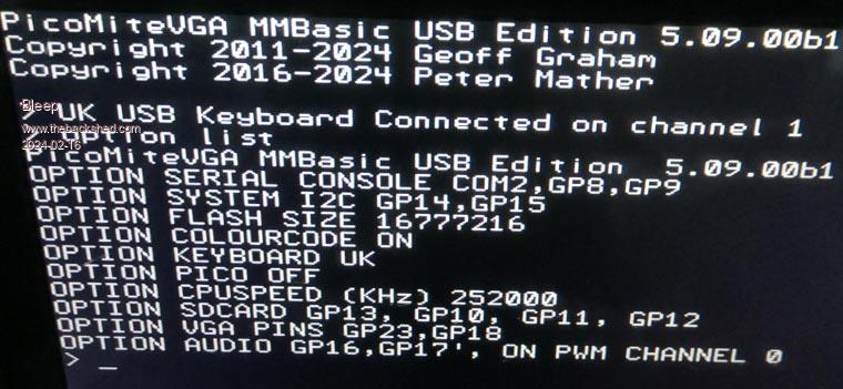 Device Manager. 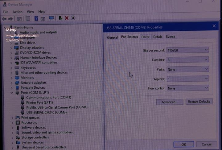 Tera Term Start up 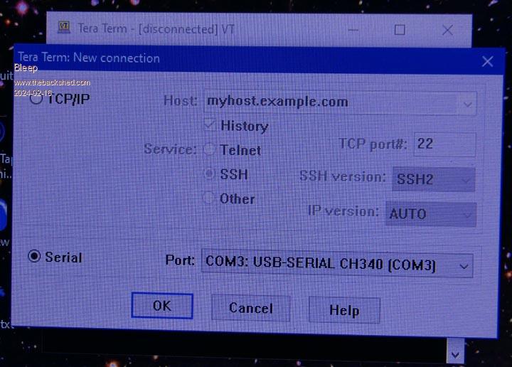 Tera Term Window. 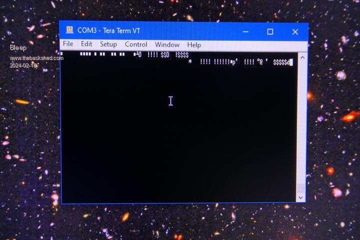 The Tera Term Window, stays completely blank if I try to use the PC keyboard to communicate with it. However I then plugged in a USB keyboard in and got the garbage shown, most keys do nothing, the retun key gave me the white squares, the up and down arrow keys gave me the $$$ and !!! etc. I have also tried a OPTION RESET, and get exactly the same again. Regards Kevin. |
||||
| matherp Guru Joined: 11/12/2012 Location: United KingdomPosts: 9115 |
MAKE SURE THE TERMINAL PROGRAM IS SET TO 115200. It tells the CH340 what baudrate to use on the TTL side over the USB descriptor. This is not the same as a CDC port where the baudrate setting doesn't matter. It overrides the Windows setting |
||||
| Bleep Guru Joined: 09/01/2022 Location: United KingdomPosts: 509 |
Thanks Peter, that's got it working, I'll continue playing now. ;-) Regards Kevin. |
||||
Grogster Admin Group Joined: 31/12/2012 Location: New ZealandPosts: 9307 |
No, they were out of stock for me too, but I have a box full of them for doing the same connector on the CMM2 units. But if I only have to solder one connector, that is still going to be fab compared to having to do them all. They might have the connectors back in stock by the time I do the next order. Smoke makes things work. When the smoke gets out, it stops! |
||||
| Mixtel90 Guru Joined: 05/10/2019 Location: United KingdomPosts: 6787 |
Drat.... RTC not working. I'll get another battery and see if that's the problem. :( Mick Zilog Inside! nascom.info for Nascom & Gemini Preliminary MMBasic docs & my PCB designs |
||||
| matherp Guru Joined: 11/12/2012 Location: United KingdomPosts: 9115 |
The RTC should work without a battery - just won't keep time when powered off. Remove the battery and then power up Then RTC SETTIME 24,2,16,9,40,0 the RTC gettime should complete OK check with ? TIME$ then OPTION RTC AUTO ENABLE TIME$ should still be OK then CPU restart time$ should still be OK If all that works then it is definitely the battery You did have it the right way up? Flat side (+) to the top |
||||
| Mixtel90 Guru Joined: 05/10/2019 Location: United KingdomPosts: 6787 |
RTC will set and keep time while powered up, I think. I have a feeling that it might have had a problem when run for a couple of hours but I'll test again as I might have forgotten to set it! There is 3V3 from the battery on pins 13/14 without being powered up as expected. Checked at the top of the pins themselves so it's not a bad solder joint on the chip. I notice that pins 5-12 are floating rather than being connected to GND, but I don't suppose that matters. Yep, the battery is right way up (even if it is a NOS one. lol). :) I'll just work through your checklist now. Mick Zilog Inside! nascom.info for Nascom & Gemini Preliminary MMBasic docs & my PCB designs |
||||
| Mixtel90 Guru Joined: 05/10/2019 Location: United KingdomPosts: 6787 |
Checklist passed ok. Plugged battery in. Checked time$ - ok disconnected and unplugged usb waited about 10s plugged in again checked time$ - ok I may be going out in a while so I'll unplug it again then and check again later on. It might have been just a poor battery contact. Mick Zilog Inside! nascom.info for Nascom & Gemini Preliminary MMBasic docs & my PCB designs |
||||
| atmega8 Guru Joined: 19/11/2013 Location: GermanyPosts: 722 |
  OK. Thank you "MatherGrog" ;-)  |
||||
| matherp Guru Joined: 11/12/2012 Location: United KingdomPosts: 9115 |
Your board is in the post, but please remember I really really hate being pestered |
||||
| atmega8 Guru Joined: 19/11/2013 Location: GermanyPosts: 722 |
Still sitting in front of my postbox. Little bit like Christmas, waiting for santa claus... Santa, hello santa, Rednose? |
||||
| atmega8 Guru Joined: 19/11/2013 Location: GermanyPosts: 722 |
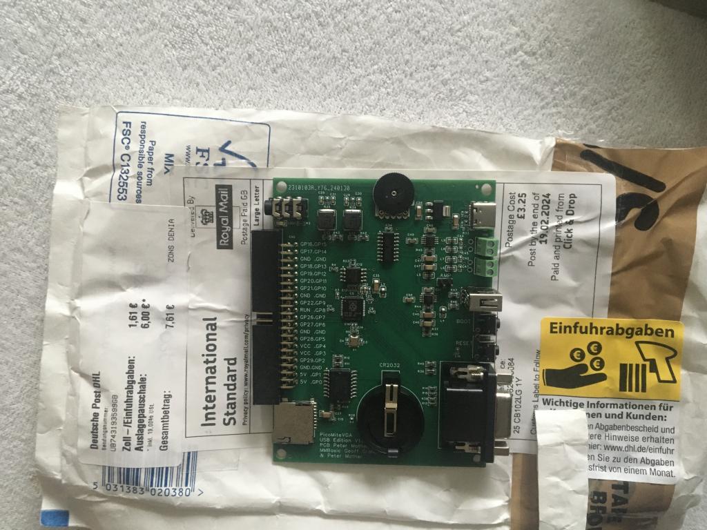 What a beauty! Thank you Peter. |
||||
| javavi Senior Member Joined: 01/10/2023 Location: UkrainePosts: 213 |
Hi Peter, Have you considered the possibility of expanding PicoMite's RAM using a PSRAM chip? For example, the SPI PSRAM chip ESP-PSRAM64H. There are options for connecting it via SPI, QPI and QPI to the GPIO pins, and there is also an option for QPI connecting it in parallel to the main flash memory of the RP2040 processor! |
||||