| |
  Page 7 of 7 Page 7 of 7 |
| Author |
Message |
larny
Guru

Joined: 31/10/2011
Location: AustraliaPosts: 346 |
| Posted: 03:17pm 14 Jun 2012 |
 Copy link to clipboard Copy link to clipboard |
 Print this post |
|
You said above:-
I have obtained a 12v solenoid that is working very nice connected to the float.
One other random question for you though. What size hole did you drill to mount your float nice and water tight?
I don't recall the hole size. I just selected a drill that was slightly larger than the outside diameter of the FS thread. It sealed very well.
I assume you mean 12 Volt DC. If so, I have two points:-
1. I did not doubt whether it would work on DC.
My point is whether it is designed for DC.
It will operate much faster on DC than AC, & therefore the armature will bang against the pole face much harder. So it may have a much lower life time on DC unless the designers allowed for DC operation.
2. Did you connect a diode across the coil the protect the Float Switch contacts from the back EMF?
If not, the FS contacts will eventually burn out due to arcing as the contacts open & close.
It is also necessary, but a bit more complicated, to protect the contacts if you're using AC.
Once you answer the questions above about the solenoid, I will be in a position to do the design. It will be very simple.
I need to know what current the solenoid draws at 12 Volt.
You woun't need a relay to drive the solenoid. That can be done by a BJT transistor or a MOSFET. But the choice of BJT or MOSFET depends on the solenoid current.
|
| |
Lapsy

Senior Member

Joined: 28/01/2012
Location: AustraliaPosts: 103 |
| Posted: 07:37pm 15 Jun 2012 |
 Copy link to clipboard Copy link to clipboard |
 Print this post |
|
No problem Larny!
Yep the solenoid is 12v DC.
Will get around to measuring the current soon.
I know nothing about the diode across the coil thing and electro magnetic frequency if that's what E.M.F stands for. Happy for you to post an explanation on that for my interest and learning if mega keen. Up to you tho...
Funny you mention also, I have a fair few diodes lying around, brand new and unused. Some still packaged, unopened for prior projects where I had to buy packs of 5 or whatever. I should check the codes on them and run it past you to see if any are suitable for this. Have to find where I stored them in some forgotten corner somewhere but certain I have 2 or 3 types about the place.
I'm going for this design, as some people could never program a VCR player, so I thought teaching someone how to operate a timer can be difficult too.
This way no one has to learn anything about programming or pushing the right buttons to setup the operation correctly to a tee.
Everything will be preset on the design and be dependent on water flow alone. Nothing will need reprogramming or resetting if there is a malfunction. It will just be a matter of replacing a broken part or whatever, so you get it up and operational again. Less hassle for me when it buggars up in other words!! (Hopefully)
Disregard AC power altogether. No longer required. DC only. DC is the platform I want to be on anyways, so starting with DC is just easier and less mucking around.
I want adjustable time frames for later expansion of reservoir, (just thinking ahead) as I may want to increase the tank size. A bigger tank to empty will require more time with the solenoid open.
I actually have to test this (which I should do before I get you to finish the design to be certain). I will use a 50ltr storage container or something or a bucket and time how long it takes to drain out. If this takes 4min 30 seconds for example then I will be in the ball park for having the solenoid open for 5 min on the timer.
I think that's everything covered for the moment.
I leave it with you in meantime to get ideas, there's no rush mate! When you have time, go for it.
This is my signature ---> Scribble, scrawl, a bit of light pencil shading, some indelable ink and a bit of caligraphy. |
| |
larny
Guru

Joined: 31/10/2011
Location: AustraliaPosts: 346 |
| Posted: 09:12pm 15 Jun 2012 |
 Copy link to clipboard Copy link to clipboard |
 Print this post |
|
Yes, that is a good idea. Simple and foolproof.
I have sketched out a timer design for you. Currently it is adjustable from about 2 minutes to 35 minutes by turning a potentiometer.
However, it is easy to change the range simply by changing a capacitor.
I'll be able to finalise the design once you measure the solenoid current.
EMF = Electromotive force. Which you can read as "voltage".
Solenoids have inductance. When you switch the current through an inductor off, there is a back EMF generated and, if there is nothing in the circuit to limit the EMF, a very high voltage spike will occur. This will cause arcing in the switch contacts which will eventually destroy them.
In your case, I intend to switch the solenoid with a transistor. However, if there is no protection, the EMF will destroy the transistor the first time the solenoid is switched off. So it definitely needs a diode to limit the voltage to about 0.7 Volt.
|
| |
larny
Guru

Joined: 31/10/2011
Location: AustraliaPosts: 346 |
| Posted: 09:56pm 15 Jun 2012 |
 Copy link to clipboard Copy link to clipboard |
 Print this post |
|
In your post, you did not address my point about the solenoid (point 1).
I have always known that you want to power the circuit with DC, not AC.
My question was whether the solenoid is designed to work on DC.
As I said in my post, I have no doubt it will work on DC.
But, as I said in more detail in my post dated 15/6, if it was designed for AC only, then it may have a short lifetime on DC. |
| |
Lapsy

Senior Member

Joined: 28/01/2012
Location: AustraliaPosts: 103 |
| Posted: 05:28pm 06 Jul 2012 |
 Copy link to clipboard Copy link to clipboard |
 Print this post |
|
Dropping back in to mention this thread is still active (for those interested).
Work in progress.....
Still on the task, slowly but surely wins the race as they say.
Will post more info for all at the next convenient stage completed.
Shout out to Larny for being free with info. Cheers once again.
Back in the near future with a further update.....
This is my signature ---> Scribble, scrawl, a bit of light pencil shading, some indelable ink and a bit of caligraphy. |
| |
Lapsy

Senior Member

Joined: 28/01/2012
Location: AustraliaPosts: 103 |
| Posted: 08:33pm 14 Jul 2012 |
 Copy link to clipboard Copy link to clipboard |
 Print this post |
|
Ok Larny,
I have taken note of your microswitch diagram. I have also had time to catchup with my other electronics mate. I have shown him the idea, and ran the other idea past him about the float switch overider, and had a lengthy talk about it.
Rather than buying more stuff (Microswitches mainly) we are going to use what we have. My friend has loads of spares laying about and he is happy to donate some to the cause once we worked out exactly what we might need.
So firstly a further diagram from you would be good, so we can see how you think we should lay this out on a board for this float off switch overider. Forget microswitches and all that. Just sticking with the solenoid and float as the moving parts. I can run this past my mate for assistance, then we can go and gather the parts and have a go at it.
This is my signature ---> Scribble, scrawl, a bit of light pencil shading, some indelable ink and a bit of caligraphy. |
| |
larny
Guru

Joined: 31/10/2011
Location: AustraliaPosts: 346 |
| Posted: 09:27pm 14 Jul 2012 |
 Copy link to clipboard Copy link to clipboard |
 Print this post |
|
Lapsy,
As I understand it, from your PM, what you want is:-
1. a Float Switch that starts a timer when the tank is full.
2. the timer operates a solenoid valve for a time that is adjustable (by a potentiometer) from 2 minutes to 20 minutes approx.
You said that you don't need a "Time of Day" timer such as the Arlec one we discussed some posts ago; since you intend to have a trickle of water flowing into the tank continuously.
I have mapped out a simple timer, based on these assumptions.
I'll post a circuit once you confirm the above.
Len |
| |
Lapsy

Senior Member

Joined: 28/01/2012
Location: AustraliaPosts: 103 |
| Posted: 04:43am 20 Jul 2012 |
 Copy link to clipboard Copy link to clipboard |
 Print this post |
|
Yep,
Correct,
Confirmed,
Content (for now) 
I could say more but no point, I will just confuse myself and others.
I'm sticking with this system for this project. Anything else simmilar or otherwise I will dedicate to its own seperate project. Sorry to those interested in the arlec thing, for the moment it is sidelined for all the above reasons e.c.t.
I do like how this thread has unfolded. Started out looking for an edition of silicon chip and ended up on float switches! Ah well...
This is my signature ---> Scribble, scrawl, a bit of light pencil shading, some indelable ink and a bit of caligraphy. |
| |
larny
Guru

Joined: 31/10/2011
Location: AustraliaPosts: 346 |
| Posted: 07:35pm 20 Jul 2012 |
 Copy link to clipboard Copy link to clipboard |
 Print this post |
|
We are going away, so I'll post a circuit in a week or 2. |
| |
Lapsy

Senior Member

Joined: 28/01/2012
Location: AustraliaPosts: 103 |
| Posted: 10:44pm 21 Jul 2012 |
 Copy link to clipboard Copy link to clipboard |
 Print this post |
|
No rush, just on another side project. Post when convinient. Cheers..
This is my signature ---> Scribble, scrawl, a bit of light pencil shading, some indelable ink and a bit of caligraphy. |
| |
larny
Guru

Joined: 31/10/2011
Location: AustraliaPosts: 346 |
| Posted: 10:32pm 23 Sep 2012 |
 Copy link to clipboard Copy link to clipboard |
 Print this post |
|
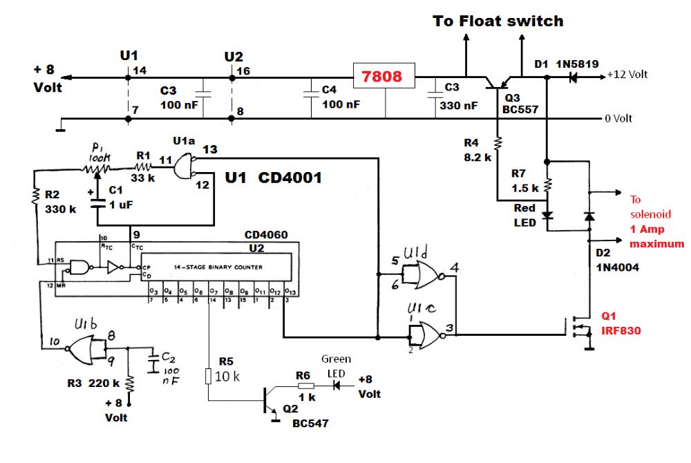
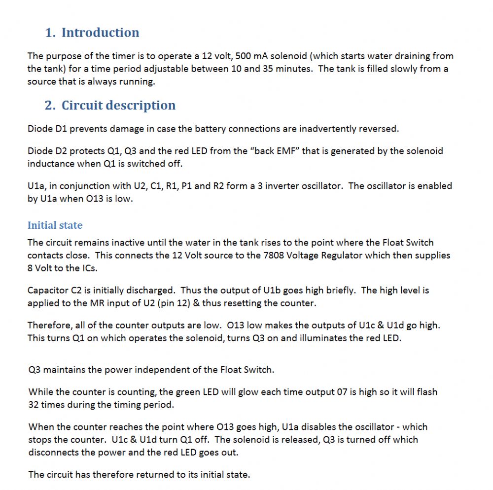
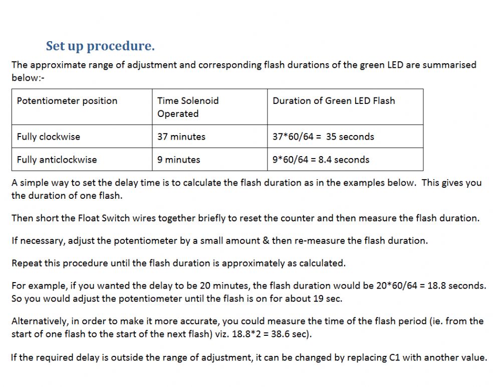
Please find the propoed circuit & circuit description/setup procedure attached.
Len


Edited by larny 2012-09-25 |
| |
Lapsy

Senior Member

Joined: 28/01/2012
Location: AustraliaPosts: 103 |
| Posted: 04:05pm 26 Oct 2012 |
 Copy link to clipboard Copy link to clipboard |
 Print this post |
|
OK!
Here is the current situation in a nutshell.
Knocked up onee of the above circuits. Running it and it's working fine on a test setup. I cannot test full scale as yet, not had the time.
Have had the time to rig up a double garage with solar lighting (CFL) down in whoop whoop land in the middle of nowhere. Running off a 40w panel that gets loads of sun. Ample for what's needed down there at the moment.
So the power is now there. I will just tap off the current supply for the planty floaty fishy setup. Groundworks pretty much done, just need to get back down there to finish off. i will keep you lot posted. There should be plenty more info and pics in the future. Stay tuned....
Cheers for the above Len! Champ!
This is my signature ---> Scribble, scrawl, a bit of light pencil shading, some indelable ink and a bit of caligraphy. |
| |
| |
  Page 7 of 7 Page 7 of 7 |

