
|

|
Forum Index : Electronics : Wiseguy New Inverter Build Nano R6
| Author | Message | ||||
| nickskethisniks Guru Joined: 17/10/2017 Location: BelgiumPosts: 458 |
What are de dimensions of the powerboard? |
||||
| KeepIS Guru Joined: 13/10/2014 Location: AustraliaPosts: 1679 |
Quick measurement 260mm x 109mm It's all too hard. Mike. |
||||
| wiseguy Guru Joined: 21/06/2018 Location: AustraliaPosts: 1156 |
I found an interesting part in my stock last night it is a weird 7805 family member going under the part number KA78R05 I only have about 480 left. The part is marked as obsolete not too distant from how I feel lately.... KA78R12CTU-D.pdf After a bit of a search on Digikey I found KA278R05 which is not obsolete and is a pin equivalent drop in, likewise at LCSC you can drive away with a KIA78R05 for 38c one off pricing. The TO220 plastic pack part has 4 Legs, in, out, ground and output enable. Max 35Vin Iout 1A. I tested one on the bench last night, it appears to have a 400uA source to the enable pin, if left open, the device defaults to a 5V output. However if you place a 10V zener in series with the 12V supply connected to the enable pin along with a 4K7 pulldown to ground it appears to work really well, as the 12V decays to under 10V the device truncates the 5V output. There is no soft stop or slow decay, maybe a good part for Rev8. Does not hurt to have rail supervisors fitted and a crystal clean well behaved 5V. I think I will send out some of these with the circuit boards for everyone so they have the option to use them instead of the 12V - 5V sawtooth generators that seem to abound. If at first you dont succeed, I suggest you avoid sky diving.... Cheers Mike |
||||
| KeepIS Guru Joined: 13/10/2014 Location: AustraliaPosts: 1679 |
Just read the specs, never seen one, what a brilliant simple idea.  FYI. I finally downloaded that info on the Nano. It only gives two options, and the couple of Nanos I checked are set at 2.5 - 2.7 range. I will go through the other clones when I add the headers. The lowest setting is marked as reserved. (No 1.8v option shown) It's all too hard. Mike. |
||||
| wiseguy Guru Joined: 21/06/2018 Location: AustraliaPosts: 1156 |
Get your Inverter FET orders in quick, I just got notification tonight that LCSC has received 360 pieces of HY5608. $1.58 for 10 off or $1.43 for 30 off both prices in $USD. This morning there are 290 pieces left, 70 pieces gone in a few hours ! Edited 2024-06-10 10:03 by wiseguy If at first you dont succeed, I suggest you avoid sky diving.... Cheers Mike |
||||
| wiseguy Guru Joined: 21/06/2018 Location: AustraliaPosts: 1156 |
Spent some time playing with the 12V to 5V regulators, switching type versus linear. The Nano has an 800mA regulator on board but don't think you can put 12V in and get much useable current out of it. The Nano LCD display draws ~60mA probably 59 for the backlight and 1mA for the logic. So I got a Nano module put 12V on Vin and connected the LCD between the 5V and ground, after a couple of minutes the tab of the regulator was over 70 degrees from a starting point of 17 degrees for ~ 0.42W dissipated. So my theory of how to drive the Nano LCD backlight from the onboard 12 to 5V regulator is a non starter. Next I got a 4pin KA78R05 regulator with an enable, I put a 1K between the enable and ground so the regulator is off. Next I put an 8V2 Zener from the enable to the 12V input, now when the input is ~ 1V higher than the zener voltage the regulator snaps on. When the input is ~ 9.1V the regulator puts out a few millivolts, but when I increase the voltage to 9.2V the regulator snaps on with 5V output again. Note the 1K is the correct value calculated from the data sheet, the 4K7 I mentioned a few posts ago was more of a guess despite that it actually did work for that part. The new result when I run an LCD from the larger plastic pack KA78R05 from 12V with the LCD on after a similar amount of time is much better. After a few minutes the input pin close to the regulator case achieved a temperature of 40 degrees from a 17 degree start. The heat of the part was a bit over lukewarm for the same 0.42W dissipated. Video clip shows a 12V input DVM, output 5V DVM, and when I toggle the supply voltage from 9.2V to 9.1V and back again how the 5V snaps off. It shows what will happen as the normal 12V input collapses and passes the 9.1V mark. I will mark up a schematic and proposed board mod to fit the linear regulator. Sorry the video is 90 degrees rotated but I can't be bothered connecting it all up & re shooting it again, video is here. Although I didn't show a scope image of the 5V falling it just drops like a rock. I think using the linear regulator part instead of the 12-5 noisy switching regulator, and the clean 5V collapse versus the slow noisy droop is a great improvement. I will include some of these regulator with each shipment of boards I send out. Edited 2024-06-12 11:58 by wiseguy If at first you dont succeed, I suggest you avoid sky diving.... Cheers Mike |
||||
| wiseguy Guru Joined: 21/06/2018 Location: AustraliaPosts: 1156 |
Apologies to those waiting patiently for their circuit boards. The factory seemed to drag their heels on manufacture. I have also been following their slowish transit, they arrived in Hong Kong on the 11th and nothing has been updated in tracking since - I did get a short update telling me of a customs issue. Today I contacted JL and asked for them to get involved and get the shipment moving again. I am partly to blame, next time regardless of the extra cost it will be DHL. My last shipment from DHL was delivery on the 3d day from the factory. So an extra hundred odd dollars for freight divided by 12 was probably the better option. They were ready on the 8th, picked up by courier from the factory on the 9th, Edited 2024-06-14 16:10 by wiseguy If at first you dont succeed, I suggest you avoid sky diving.... Cheers Mike |
||||
Revlac Guru Joined: 31/12/2016 Location: AustraliaPosts: 1021 |
Not rush for it here, first time I used JLCPCB I selected the cheap slow method and it was faster at the time, local delivery is a whole different story, its always slow.  Cheers Aaron Off The Grid |
||||
| wiseguy Guru Joined: 21/06/2018 Location: AustraliaPosts: 1156 |
Well the slow boat from China finally arrived last night so this is a mite bigger task than it looked on paper.... first cut out 60 display boards sigh. Will ship overseas first and the rest immediately after, unfortunately the weight for Serbia and UK will be a tad more than I had calculated for, so next time for overseas stuff, being even wiser I will just pay up front and after shipping send on the total but its live and learn - I'm not really fussed its only money. Here is a picture after unpacking the box before it gets really messy...... PS this is my wifes bench mine is even cleaner haha - NOT 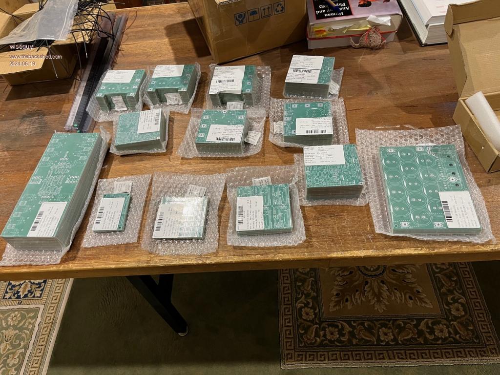 If at first you dont succeed, I suggest you avoid sky diving.... Cheers Mike |
||||
| KeepIS Guru Joined: 13/10/2014 Location: AustraliaPosts: 1679 |
I didn't realize you had to cut the display boards. Bringing a project like this together is hard enough, but doing it on your own is makes it even harder. I guess there is not much more we can say except thanks for all that hard work, effort, and hope any hair loss is not permanent. The great part is, the Inverter does run beautifully  . Edited 2024-06-19 13:39 by KeepIS It's all too hard. Mike. |
||||
| wiseguy Guru Joined: 21/06/2018 Location: AustraliaPosts: 1156 |
Unfortunately the hair loss is permanent, hope you touch wood every time you mention the "perfect inverter" peformance.... OK everything is sent/shipped. The post office did a nice printout of tracking numbers and post codes so I will just post the pictures and you can find your tracking number against your post codes. I spent over an hour finding and going over the customs tariffs to get the chapter number etc. the lady at the post office typed in the description and then said oh what a good boy you prefilled the numbers for me hmmph. The moral of the story is you just need the description, and the software finds the category and type numbers automatically saving a lot of time and effort. From tomorrow onwards goods should be received for the more expensive UK & Serbia for Serbia I was 7 grams over and it cost $13 extra, for UK I was 19 grams over and it also cost $13 extra as they both went into the next 500 gram bracket. So I sent extra goodies with them in the way of 48V 6A slimline and 16A relays amongst other bits and pieces. I wanted to get our moneys worth - then I had to fill in customs forms and realised that I needed tariff numbers and costs weights etc of everything in the package - no good deed goes unpunished. If Mabs & Ziki are inclined to make up my shortfall I had to pay I wont knock it back but if your funds are tight I'll gift it..... I must be getting slower in my old age this whole process took ~ 2 days and nights to complete - feels great to be over it though ! 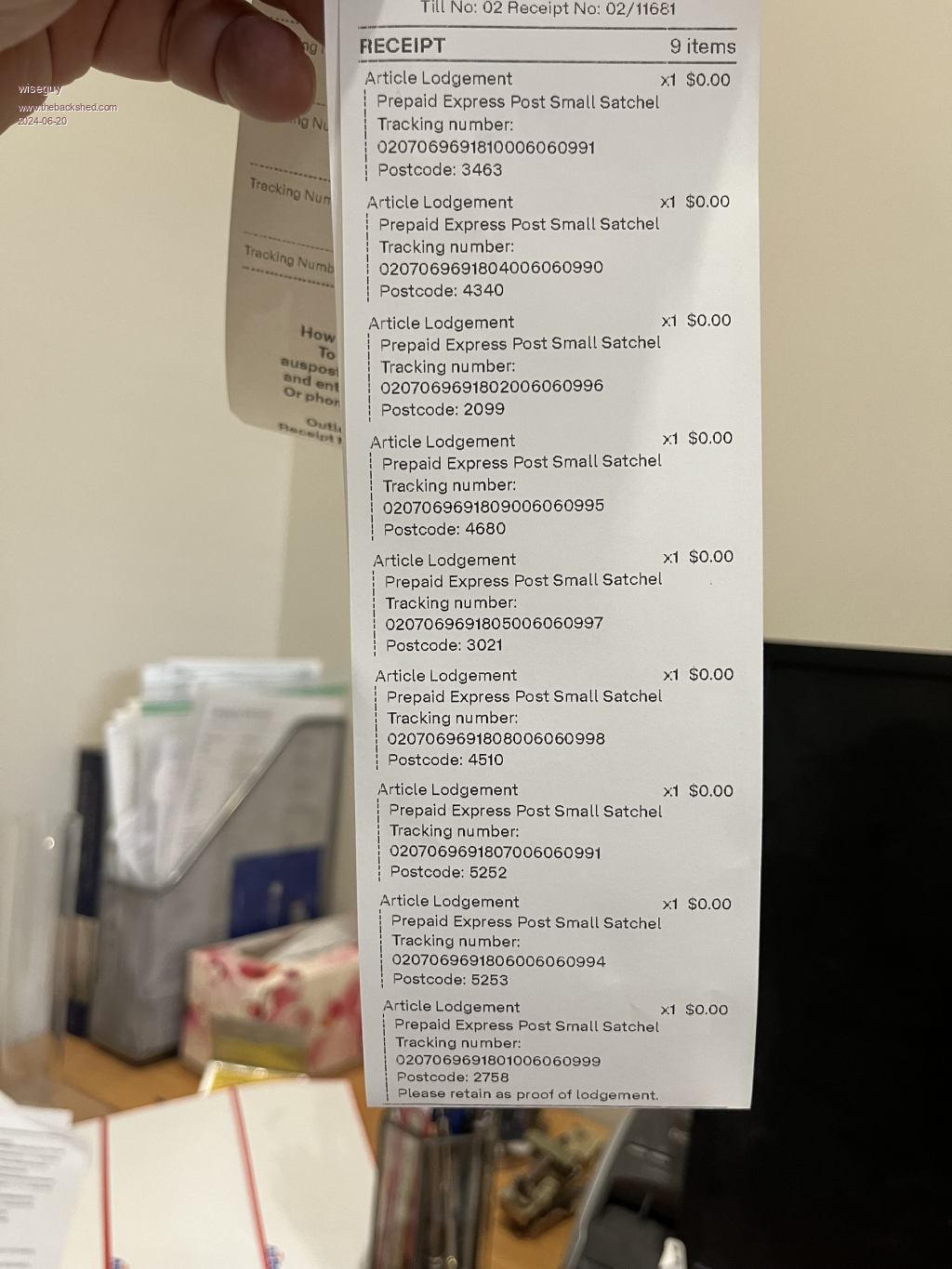 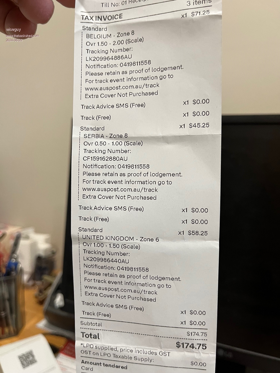 I will be a bit scarce on here for the next week or so - if I need to post extra information etc to help with the builds feel free to ask for whatever is missing. Edited 2024-06-20 23:22 by wiseguy If at first you dont succeed, I suggest you avoid sky diving.... Cheers Mike |
||||
| rogerdw Guru Joined: 22/10/2019 Location: AustraliaPosts: 852 |
Well let me be the first to say my boards have arrived thanks Mike ... along with a few other unexpected parts ... so thank you very much. And I appreciate all the effort you've put into not only the design ... but packing and posting these things all over the world.  Cheers, Roger |
||||
Bryan1 Guru Joined: 22/02/2006 Location: AustraliaPosts: 1343 |
Second to say the boards have arrived so Thanks Mike and there is a bit of weight to the package so after a pie, time to go up to my shed and open it up to see all the goodies  Regards Bryan Edit: Well all opened up so now time to download all the info and a week or two to let it all soak in while all the parts are in the post. Edited 2024-06-21 12:58 by Bryan1 |
||||
| expo Newbie Joined: 10/01/2016 Location: AustraliaPosts: 25 |
Third to confirm the boards (and additional bits) have arrived, thanks Mike. P.S. I think some major suppliers could take some lessons in packaging from you! Best wishes, Greg (expo) |
||||
| wiseguy Guru Joined: 21/06/2018 Location: AustraliaPosts: 1156 |
Thanks for the feedback chaps, glad they have arrived ok, should be all received by Monday I would hope. (not overseas ones unfortunately) With Regard to the Mods for the 5V regulator, I am posting here how to use the spare pads near the sync input for the 4 pin regulators with the added zener diode (8.2 - 10V) suggested and 1K resistor. You could also just use the 3 pins that the little switching regulator would use to fit a standard 7805 style linear regulator with small heatsink and not fit the 4 pin regulator with the enable. Extra information about 5V Mods. The linear KA78R05 regulator is not a "must do item" the addition of the TO92 5V supply monitor parts should be adequate enough to stop the Nano codes from getting corrupted. But the LCD backlight and maybe some LEDs may still flash or flicker a few times during shutdown. The linear regulator modification if installed should cure that too. The next version of the Nano control card will have provision for the KA78R05 mod as well as the 5V supply monitor reset parts. On the little LCD PCB the +5V reset monitor should also be fitted for code protection. The supply monitor TO92 part that holds the Nano in reset is a simple addition to the underside of the board. The second picture shows the 3 pins highlighted to denote LHS=Gnd, Mid=+5V, RHS=RST, just check the pin out on the data sheet for the part you select. Mountint eh 5V monitor to the lCD board is almost the same ecept for the LHS pin will have to be soldered to a small area nearby with the solder resist scratched off as the same Nano pin is not grounded on the LCD board. 4 PIN LDO 5V linear regulator suggested mod. connections to be made are highlighted 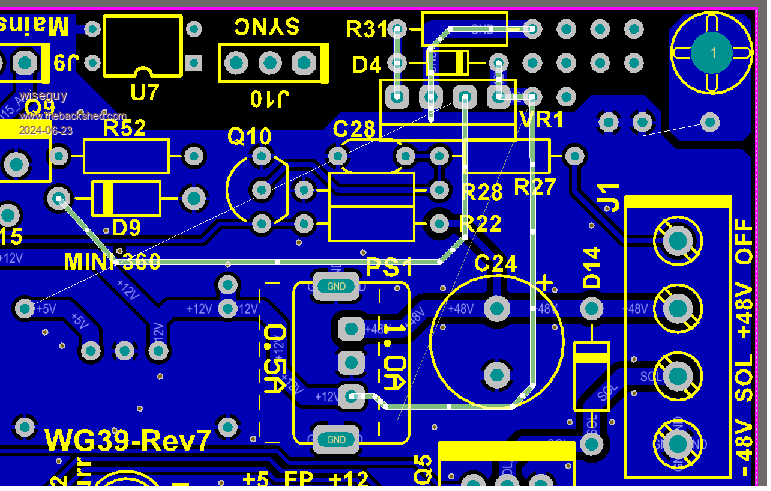 5V supply monitor suggested mod. connections to be made are highlighted 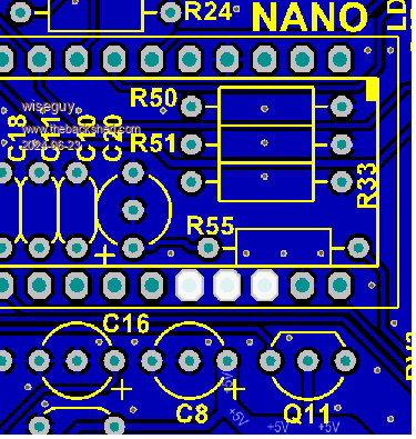 And an assembly diagram showing the connections to be made, note pin 3 of regulator and R31 are joined and need to connect to the ground-plane. WG39R7A Assy.pdf Edited 2024-06-24 13:16 by wiseguy If at first you dont succeed, I suggest you avoid sky diving.... Cheers Mike |
||||
| FET cemetery Newbie Joined: 17/04/2024 Location: AustraliaPosts: 3 |
Mine have arrived, thanks Mike. Thanks again for the work you've put in, and the extra goodies are much appreciated. Paul. PS Speaking as an Auspost employee I am humbled by your packaging skills, you deserve some sort of award. I had to use scissors to unpack them... No stone unturned, no FET unburned. |
||||
| disco4now Guru Joined: 18/12/2014 Location: AustraliaPosts: 896 |
Thanks Mike, Mine arrived today. Thanks for your efforts on this. I am going through my parts and getting my final(hopefully) order for Digikey together. Regards Gerry Latest F4 Latest H7 |
||||
Revlac Guru Joined: 31/12/2016 Location: AustraliaPosts: 1021 |
Thanks Mike, Package arrived today all in good condition, will be fun putting it together.  Cheers Aaron Off The Grid |
||||
| wiseguy Guru Joined: 21/06/2018 Location: AustraliaPosts: 1156 |
NOTE 2 Changes to WG39Rev7 one an omission on the BOM (Q11) two a component value tweak. If you already soldered in R7 sorry it should be changed from 150K to 120K see below. I have just finished building the inverter circuit board WG38Rev7 which was recently shipped out. Rev7 had a few extra parts added to enable accurate setting of low AC currents ie 0.2A as well as ability to set the AC zero voltage. Ok I admit this was overkill so by all means leave out the trimpot RV4 - it is unlikely you want accuracy of your inverter near zero volts out (leaving out R4 will not cause any other issues). Using Poidas code, when the inverter is not producing any AC output the error messages cover the VAC value anyway but possibly the KeepIS code might do this differently and ACV is visible albeit with zero volts so if there is a residual reading it should be able to be offset back to zero. I found 1 error using my BOM, the line Q3, 4, 6, 10 - should read Q3, 4, 6, 10, 11 and the quantity should be 5 not 4. Q11 was added in the last revision it allows the indicator for Vcap/Vlow to use either 5V or 12V to drive the LEDs. The front panel is currently joined with a small track to power it from 5V by default. If you have 12 V LEDs and want to use them then the track needs to be cut and a link inserted to power the front panel from 12V. Right next to the J3 silkscreen designator, you will see 3 pads, the outer two are labelled +5V and +12V if you look closely you will see a track on the component side of the PCB joining the centre pad to the +5V pad, cutting this track and then linking the centre with +12V pad will give you 12V on the front panel. One word of caution the current being sunk by the Q11 should not exceed ~30mA max as the current is limited by the current capability of the Nanos D13 output pin, so it needs to be a LED not a lamp. After building up the PCB and testing, it worked first go BUT there needs to be a component value change R7 is listed as 150K, please use a 120K as the linearity of the ACV above 230VAC started to suffer (a lower reading). Although it was not noticeable on my previous test unit (@235V) it needed to be scaled down a bit and is now linear to over 250VAC. Forgot to mention I installed the 4 pin linear regulator with its zener and resistor and it works great, at 11V in still working fine at 10V in has shut down the 5V cleanly. Poida is tidying up the code for a proper release version in due course, if anyone needs code before that release there is a version available that works ok but the newer release will the best one to use. Mab your board arrived in UK ~24 hours ago so its getting closer, Ziki & Nick your packages are awaiting the next flight from Melbourne - I dont know why they were a bit slower, they were all posted at once.... Edited 2024-06-26 00:45 by wiseguy If at first you dont succeed, I suggest you avoid sky diving.... Cheers Mike |
||||
| mab1 Senior Member Joined: 10/02/2015 Location: United KingdomPosts: 209 |
 I'm watching the tracking info, and keep reminding myself there's no point being impatient I'm watching the tracking info, and keep reminding myself there's no point being impatient  |
||||