
|

|
Forum Index : Electronics : A new controller circuit
| Author | Message | ||||
| sparkey Senior Member Joined: 15/06/2011 Location: AustraliaPosts: 819 |
ok found anothewr chip will ressurect the cct asap but having a little break atm also could you tell me the purpose of "R9" please... technicians do it with least resistance |
||||
| sparkey Senior Member Joined: 15/06/2011 Location: AustraliaPosts: 819 |
houston we have lift off i may need to run the "cal-b" again but it seems to be throwing the relay at arond 14.2/3... technicians do it with least resistance |
||||
| larny Guru Joined: 31/10/2011 Location: AustraliaPosts: 346 |
Sparkey, I don't know which output you have on pin 13. My drawing did not specify the pins. When you're refering to a comparitor, please indicate which one it is. eg. U1a, output or U2b + input, etc. If you want me to analyse the problem, you need to follow all of my suggestions & answer all of my questions. Here is a spread sheet. If you fill it in, I'll be able to diagnose the problem. 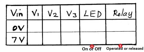
Len |
||||
| larny Guru Joined: 31/10/2011 Location: AustraliaPosts: 346 |
Excellent, I await the results. My previous post crossed this one, so you may be able to ignore it. But if you have further problems, please fill in the spread that I attached. Len |
||||
| sparkey Senior Member Joined: 15/06/2011 Location: AustraliaPosts: 819 |
ok here ya go the led and relay at engaguedged mode 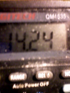
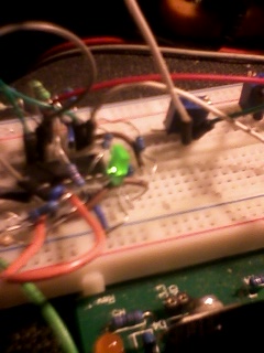
technicians do it with least resistance |
||||
| sparkey Senior Member Joined: 15/06/2011 Location: AustraliaPosts: 819 |
to glenn... what exact voltage do you want the relay to cutin and what voltage do u want it to cut out .....if those voltages have already been stated eairlier and the setup proceedure folled meet your crieteria then thats what i will set it at i dont how ever know if relay coil resistance is going to change the operating voltages ...and do u need me to make you one of these units or did you just want it to be made and tested so that you could build your own....also i am using an"IRF640" fet that i think came out of a "ATX" power supply....it has an inbuilt diode protection but i am still running the diode across the relay coil i am using a "1N4004" silicon .... this is the drop out voltage on the down slope that the relay cuts out it is cutting in at about 14.2 volts this may be a little high not shure though and i dont have a load to test it on as i only have adjustable supply to test on my gen is rated much higher dont use twelve volt gear.... 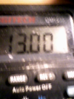
technicians do it with least resistance |
||||
| sparkey Senior Member Joined: 15/06/2011 Location: AustraliaPosts: 819 |
most of my spares are quite old though never been used ...we live in a dispossable society these days ..the quality of electronic parts seem to have been neglected .. like the 4000 series chips they would have to be the most finicky chips ever brought on the market i went through thre different manafactures before i got a 4013 flip flop that would work like it should ....piece of trivia there the relay cct is still working thoug since i got it going i found that the problem was not the chip in fact what i had done was run "r8" to pin 14 in stead of pin 13 once i did that fix everything dropped into place nice work on the mod there with the 339 i was nearly at a state that i was going to try use a "tl074 " in stead but the old 339 made the grade next i will be looking at the 317 mod ..i guess it all comes down to the divider network of the 47k and the 33k "r1/r2" regards sparkey.... technicians do it with least resistance |
||||
| larny Guru Joined: 31/10/2011 Location: AustraliaPosts: 346 |
Sparkey, re your previous post to Glenn. My recollection is that Glenn said in his initial post that he set his levels to 14.5 Volt & 13.0 Volt. That's why I designed it for those levels. I have never had any problem with the 4000 series & I've done many many deigns with them. Did you use bypass capacitors? You will get strange results if you don't have adequate bypassing because of unwanted coupling via the supply line. Len Len |
||||
| sparkey Senior Member Joined: 15/06/2011 Location: AustraliaPosts: 819 |
thanks for that ..len.... i actully have it latching in at 14.5 volts and on the down slope cut out at 13 volts so thats fine i guess ... now i guess its up to him now what he wants to do...yep just got the increment set and on my 50 dollar "dmm" its cutting in at 14.5 volts and on the down slope its unlatching at 13.0 volts given the fact that my meter is only 6 monts old i`d say that its within .05+ or minus of its value being close enough for me.... technicians do it with least resistance |
||||
| Gizmo Admin Group Joined: 05/06/2004 Location: AustraliaPosts: 5078 |
Hi Sparkey I hope your not making this one for me. I already have more controllers than I can poke a stick at, all past projects. Besides I dont have a windmill in the air at the moment and no way to test the controller. Here are some links to my previous controllers. This was my favorite http://www.thebackshed.com/Windmill/articles/GizmoPicAxeChar ger.asp , and this one is what started this thread off http://www.thebackshed.com/Windmill/articles/TL084-Controlle r.asp, as Pete said, its needs some modifications. This one can be rigged as a controller too http://www.thebackshed.com/Windmill/PicLog.asp. Plus a couple of articles about dump loads http://www.thebackshed.com/Windmill/articles/200wDumpLoad.as p and one by Pete http://www.thebackshed.com/Windmill/articles/BuildingEncapsu latedResistors.asp. Just thought I would post those links, not everyone is aware there is a web site behind this forum with lots of past projects. For normal 12v batteries I would set it at 14.5 and 13.4 volts, but it really depends on the battery type and bank size. Glenn The best time to plant a tree was twenty years ago, the second best time is right now. JAQ |
||||
| sparkey Senior Member Joined: 15/06/2011 Location: AustraliaPosts: 819 |
ok cool will have a look at them...thank you technicians do it with least resistance |
||||
| larny Guru Joined: 31/10/2011 Location: AustraliaPosts: 346 |
Sparkey, What voltages do you want your 36 Volt system to trigger? Glenn said above that they depend on the type of battery, etc. So I'll await your advice. Len |
||||
| sparkey Senior Member Joined: 15/06/2011 Location: AustraliaPosts: 819 |
38 to 40.0 volts technicians do it with least resistance |
||||
| larny Guru Joined: 31/10/2011 Location: AustraliaPosts: 346 |
Sparkey, You said in your PM that you want it to be 32/40 Volt. Please confirm whether you want 38/40 or 32/40. Len |
||||
| sparkey Senior Member Joined: 15/06/2011 Location: AustraliaPosts: 819 |
38 to 40 technicians do it with least resistance |
||||
| larny Guru Joined: 31/10/2011 Location: AustraliaPosts: 346 |
Sparkey, Here is the Circuit, Circuit Description & Calibration Procedure for 38 ~ 40 Volt version. It is easy to re-calculate the resistor values if you need to change the levels. Let me know if you want to avoid using a relay & drive the dummy load with a MOSFET. Len 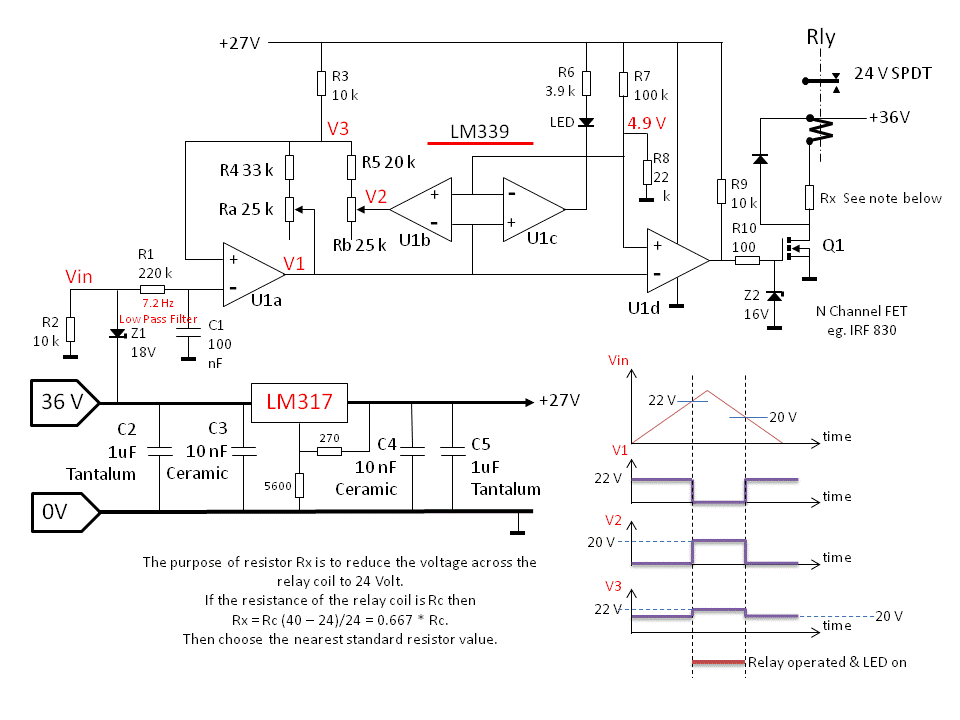
2011-11-16_062732_Circuit_Description_12.pdf 2011-11-16_062756_Calibration_Procedure_36.pdf |
||||
| sparkey Senior Member Joined: 15/06/2011 Location: AustraliaPosts: 819 |
thanks a heap len i will prolly build it tonite see how things go not shure weather i have the zenners ...but can get some tomorrow so thats great ..thanks a heap...its all good... technicians do it with least resistance |
||||
| larny Guru Joined: 31/10/2011 Location: AustraliaPosts: 346 |
Sparkey, You're welcome. Len |
||||
| larny Guru Joined: 31/10/2011 Location: AustraliaPosts: 346 |
Sparkey, Sorry, I added the wrong Circuit Description & there were some errors in the Calibration Procedure. So Here they are:- 2011-11-17_072019_Calibration_Procedure_36.pdf 2011-11-17_072100_Circuit_Description_36.pdf Len |
||||
| sparkey Senior Member Joined: 15/06/2011 Location: AustraliaPosts: 819 |
thanks len actullty it would be better if i could change from 38 to 39 and 40.5 volts if you have some spare time just post a "pdf" if possable but thanks for all your help on this one oh and i am using an "irf640" but i dont think that the fet in this app is goung to make a great diff..its being saturated igess and well they do make great solid state switches....sparkey... technicians do it with least resistance |
||||