
|

|
Forum Index : Electronics : Variable input voltage bat charger
| Author | Message | ||||
oztules Guru Joined: 26/07/2007 Location: AustraliaPosts: 1686 |
OK Dinges.... I have found the USB cable. My camera has a floppy drive which is great .... but the laptop died and so I fixed up another oldie with puppy linux... but no floppy... hence why the USB cable was near unfindable.. not used for years..... moving right along. Time to use up some of Glens new bandwidth 
Firstly for the non-believers, here is the fiendish desoldering tool and some freshly released bits: and here is the solder and stuff that rains out of the board: and here is the final resultant mess:\ Here is the denuded board, only the HV side is intact and the current sense I have added ( pot over the chip) and next we have the full wave unit (now 24v@8A max): And lastly, we have the 900w version... that used the original 6A diode, and 40w switches....he he he... You may note that the transistor heat sink and population has gone west for the moment... trying to get time to whack in some biggies..... sigh.. time... And just for something interesting here is a 1kw unit with no electro's in good old fashioned push pull... and a big transformer I wound for it for testing...: Well I think that keeps all the promises I've made. ............oztules Village idiot...or... just another hack out of his depth |
||||
| Dinges Senior Member Joined: 04/01/2008 Location: AlbaniaPosts: 510 |
[quote=Oztules]As can be imagined, this can't be overcome from adding caps or inductors on the input. I suppose it is possible that a choke will help filter out the harmonics, but I can't see it correcting the crest surge by much for a 50hz choke of reasonable size[/quote] Yeah, I think you're right; we've had discussion here before about 'pure' cos(phi) phasedifference between voltage and current (i.e. powerfactor), and crest-factor of the non-sinusoid load. Nevertheless, a reactor does seem to improve matters, according to wikipedia at least: [quote=Wikipedia]For example, SMPS with passive PFC can achieve power factor of about 0.7–0.75, SMPS with active PFC, up to 0.99 power factor, while a SMPS without any power factor correction has a power factor of only about 0.55–0.65 [/quote]from http://en.wikipedia.org/wiki/Power_factor_correction In that wikipedia entry on powerfactor you can see that they separate both the cos(phi) phasedifference and harmonics (because of non-linearities) too, and state that a filter can only be useful in filtering out the harmonics, as you've stated too. [quote=Oztules]I have found the USB cable.[/quote] You mean you couldn't find any crocodile-clip wires in the entire shack to temporarily rig a connection between the camera and the PC? Hm. I can't help but think a little less of you because of that.... 
[quote]Firstly for the non-believers, here is the fiendish desoldering tool and some freshly released bits [/quote] I do believe you when you say so, Oztules. No need for pictures to prove it. Obviously you're more skilled in using the heatgun than I am; I always tend to ruin the board when using the heatgun on pertinax (phenolpaper) board. In the 5th picture I see a diode at the bottom right (next to the red wire and one of the two blue electrolytic caps); what is it for? The 900W version is impressive.... I'll consider that to be a future challenge for me to copy :) . For the moment the full-wave conversion would be plenty enough though to satisfy my needs (rather: wants). Think for my own use, if I'd ever build a 900W version, I'd try to parallel 3 transformers of 300W. Of course inductance would go down (in parallel). Do you think the rest of the electronics would have a problem driving 2 (or 3) identical transformers in parallel? Problems with ringing, driving (using suitably rated transistors, of course), or other issues? Thanks for the photos and remarks. As always, they're an inspiration. Also your other story of the windturbines on your island. Peter. Edit: I think I know now what the diode is for; the reason I asked was because it looked so small, but I only noticed now that that particular PSU is 'only' 8A max, so it looks like the diode could pass all that current. I was thinking of currents of 15A as with your other PSUs and couldn't imagine that relatively small diode passing all that current, so assumed you pulled some kind of clever trick with the diode for one reason or another. |
||||
oztules Guru Joined: 26/07/2007 Location: AustraliaPosts: 1686 |
He he he.... that diode is simply a crowbar. It has very very high surge capacity, so if you connect a battery bank up in the wrong polarity, nothing happens to the psu, but the external wiring will spit sparks and alert you to the stupidity. I normally use an inline fuse in series with the output. This has helped to keep the power supplies together in quite a few circumstances. Especially if you build them for other people to float their batteries on.... one day they mix it up... this stops that from being a disaster. So, no, the diode does nothing, it just sits there across the output for protection. Transformers in parallel. Haven't tried it, but worth a go. I think you will get better results with winding a bigger core.... less space. ............oztules Village idiot...or... just another hack out of his depth |
||||
| Dinges Senior Member Joined: 04/01/2008 Location: AlbaniaPosts: 510 |
[quote=Oztules] that diode is simply a crowbar. It has very very high surge capacity, so if you connect a battery bank up in the wrong polarity, nothing happens to the psu, but the external wiring will spit sparks[/quote] Ah ok. Actually, I thought it was a series diode for when you want to connect several PSUs in parallel, or charge a battery without energy flowing back into the circuit (to perhaps the TL494). I had ruled out the possibility of it being a crowbardiode as I didn't see any fuse nearby (call me sophisticated, or, in Janne's worldview, 'uncertain'), despite the fact that the anode seemed to be very close to the negative lead of the elco. Guess you've taken Janne's sig-line to heart then. Oh, btw, Janne: EVERYTHING can (and on occasion: will) act as a fuse. Even things that weren't designed for it. In my experience, the 10$ semiconductor will often blow in an attempt to protect the 0.10$ fuse... 
[quote]Transformers in parallel. Haven't tried it, but worth a go. I think you will get better results with winding a bigger core.... less space.[/quote] Yes, rewinding a custom transformer would be a more elegant solution. But as I've got several of those old transformers, some of which are identical, it seems a logical thing to try out sometime. As far as it taking up a bit more space, that'd be a mechanical problem that can likely be easily solved with a few cm of wire. Or glue two transformers on top of eachother, back-to-back (with the upper transformer sticking its pins in the air). Peter. (Give me a *F*, give me a *U*, give me a *S*, give me an *E*, what do we have?  FUSE! FUSE!  ) )
|
||||
oztules Guru Joined: 26/07/2007 Location: AustraliaPosts: 1686 |
Update on the 900w unit. Replaced the switchers with bigger ones, replaced the diode with 20A200v twin d92. Ran the unit driving 500w vacuum motor (36vdc) for about 5mins with no cooling. Everything stood up well, but the fins got hot. From Spuds 400w pictures, the heat sinks are mandatory.... and i stopped the test because the heat sinks on these little ones were up to 65C or more. With Spud sized heatsinks and the fan turned on, this thing would power up to much higher power. This answers the question of the topology as is for higher power.... answer yes. Bigger transformer, bigger switchers, bigger diodes and lots of cooling will do it no problems. Nothing else needs beefing up except the output inductor/filters. (Beware of saturating the torroids with thicker wire and higher currents.) The input filters seem to do just fine. Bigger caps would help with ripple I suspect, but for batt charging ... who cares. Fuses.... what fuse  Village idiot...or... just another hack out of his depth |
||||
| Bolty Regular Member Joined: 03/04/2008 Location: AustraliaPosts: 81 |
Previous posting. As mentioned earlier, many PC power supplies utilized 494 control IC's. Many other supplies that I have acquired utilized strangely marked IC's like 2002, 2003 etc. Do any of you guys know what these chips are? Are they rebadged 494's? Do you have any idea why they are labelled such as this? Sorry if I rambled a little in my earlier post/question. Can anyone help with info about these 2002, etc chips. Thanks! |
||||
oztules Guru Joined: 26/07/2007 Location: AustraliaPosts: 1686 |
Egad, I was hoping someone else would answer that for you.. as I'm a bit vague on it as well. The DNA1001 DNA1002 chips are proprietary chips from Delta (Taiwan I think). I recall from my last search..... and this does not mean it is gospel..... that the DNA1001 chip is on the high side of the circuitry, and provides both PFC and PWM function (Possibly similar to the ML4819 (with a few less pins) or the NCP1603 if you want to stick to 16 pins. No idea of the 1001 pinouts. A Russian site had the Delta 250w ATX schematic back in 2005/6, but does not seem to be there any more. The DNA1002 chip is on the low side and communicates it's results to the DNA1001 via isolator chip. It does the housekeeping and tells the pfc/pwm chip how things are going down in the village. So you will always see them together... I have to assume the 2001 / 2002 are similar beasts..(or did you mean DNA1002 and DNA1001 and mixed them up for me??) and just as useless as there are no datasheets for any of them. It's possible that they were manufactured by Hitachi for Delta. The chip was listed on USBID.com from memory. (by the hundered at least.. 500 dollar minimum line order last I used them.) From the dusty archives from Badcaps I found this circuit snippet of a 1002 in circuit.... no pinouts, just some ones tracing/reverse engineering. It's the housekeeper chip: 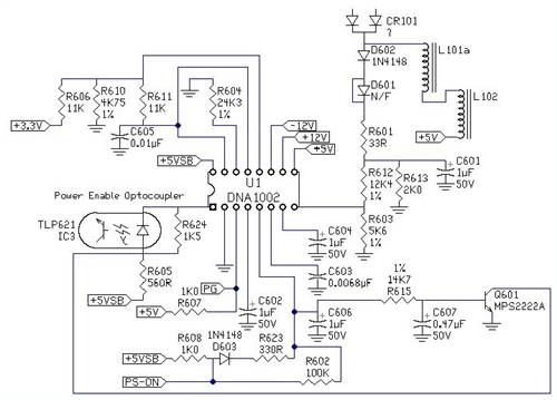
The opto coupler I think is actually the PWM voltage control opto coupler, not the power enable as it describes.... other wise the PWM would not know how things were progressing on the other side of the fence... It would double as the inhibit/sleep as well (pretend overvoltage condition till wake up) They were used in the "upmarket" supplies of their time as they had active PFC. I know that this does not help, but it is all I can remember about this stuff, as when I found it to be proprietary, I lost interest completely. I hope it helps a little bit anyway 
Maybe someone else can fill in the gaps or set us both straight. ............oztules Village idiot...or... just another hack out of his depth |
||||
| Bolty Regular Member Joined: 03/04/2008 Location: AustraliaPosts: 81 |
Wow Oztules that is a fantastic answer. You certainly have had a lot of experience with SMPS's. The chips that I have seen are definitely 2002, 2003 and 2004. The number almost equated with the probable age of the power supply. The other thing about the labels on these chips is that the number is at least twice the size of the label on a normal chip. It may well be a masking for the actual chip that it covers! Perhaps I should try removing one and placing it in place of a 494 in a working power supply I would take a photo of the chips and post them here if I was at home....5km away from Gordon. However I am holidaying in paradise at present....well not quite up to the standard of your paradise on Flinders Island. We have spent 3 weeks in Tasmania, and are currently in (wet) Franklin. I read with envy, your description of the wind turbines on Flinders. I must say that I am the kind of person that appreciates a quieter lifestyle in small communities. Or putting it another way, it is great to be away from the humdrum of cities...even though my home city is very small, I love the genuineness, care and warmth of people in small communities. In summary I love all of Tasmania, especially the people and the magnificent scenery. Thanks once again! |
||||
oztules Guru Joined: 26/07/2007 Location: AustraliaPosts: 1686 |
Gordon, I tested the transformer I wound last night. It has 18 turns 1.6mm wire (first half of primary) 9 turns of 2 in hand 1.6mm wire (first secondary) ... then 9 turns 1.6mm 2 in hand second half of secondary and finally 18 turns of 1.6mm second primary (outer) The ferrite was an ETD39. Results were impressive it peaked at 40 amps (I think.... the 30A meter was wrapped around the stops) driving a 24v battery bank (110AH). So the voltage was up around 30 odd volts. I ran it for 5 mins at 18A 30v and the heat sinks were strangely cooler than I expected... particularly the diode sinks. They were way cooler than the transistor heat sinks... usually the other way around  , and the trannies were not stinking hot either (no cooling fan in this test). The power transformer was stone cold after the test. , and the trannies were not stinking hot either (no cooling fan in this test). The power transformer was stone cold after the test.
The little diode was replaced with a D92 (20A x 200v twin). This would normally be a lot hotter than it got in this test... don't understand this at all. All in all very pleasant. Whilst way oversized, it still fitted in between the heat sinks, and used the through holes in the board. Will get some pics maybe tomorrow perhaps. ............oztules Village idiot...or... just another hack out of his depth |
||||
| sPuDd Senior Member Joined: 10/07/2007 Location: AustraliaPosts: 251 |
Oztules, how does the drive waveform look? I've been finding mine are a mess, especially when at low loads. Been a while since I benched one, I wonder if they are reacting with the iso transformers I use... sPuDd.. It should work ...in theory |
||||
oztules Guru Joined: 26/07/2007 Location: AustraliaPosts: 1686 |
Ok Spud. I decided to use a turn of wire around the core to achieve isolation and no interference to the drive or driven wave form. This should give a true picture of all the waveforms currently going through the transformer  (neat solution yes?) (neat solution yes?)
So here is the first one with about 10w output... I couldn't take a pic at less power, as much less and I could barely see the trace it was so fine... but just as clean none the less: 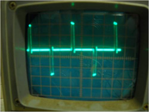
Next we have it at about 120W (about 10A@12v or so). This was driving a 36v vacuum motor. It can use up some 500w. (At the 10 watt level, the motor barely turned.... so inductive load with a commutated load very low impedance.,): 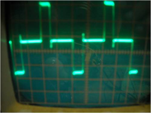
At 16A 32v (about 500w)it looks like this: The top/bottom of the wave form is very busy. It is just a blown up version of the lower power traces. If you push the definition up of the low power 10w one, it shows the same thing but at smaller amplitude in that part of the wave form. It may be the commutation causing it too, but I don't have a dead load handy. 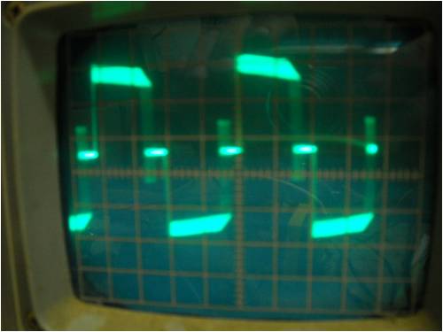
Here is a pic of the hand wound "quickie" transformer (a 20 minute job) :The 1.6mm wire is pretty darn heavy, and the twisted centertap is a huge piece of copper. 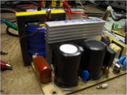
and again.. note the single turn of thin wire wound around the stack to get the scope pictures with isolation. 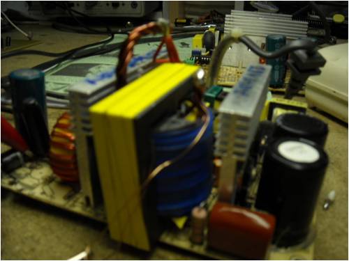
And finally a birds eye view to show the under populated board. 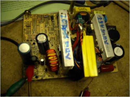
Is this what you were after?? ........oztules Village idiot...or... just another hack out of his depth |
||||
| sPuDd Senior Member Joined: 10/07/2007 Location: AustraliaPosts: 251 |
Thanks Oztules, I'll slip a fine wire around the core and try that. In fact I could do it with any core that I can slip a wire into. sPuDd.. It should work ...in theory |
||||
| sPuDd Senior Member Joined: 10/07/2007 Location: AustraliaPosts: 251 |
Oztules, did the transformer wrap, and that sort of helped. The ISO transformers were causing problems, so I went live mains once the units were working. The wave is 100% duty cycle regardless of voltage or power in or out. The only difference at lower voltage settings is buckets of noise. There must be something wrong with my 494 setup. I know its a rough diagram, but I could not be bothered fighting with software. How does this differ from your setup, minus the current control setup of course. I notice the 494 data sheet shows a complex resistor cap setup around the comp pins. EDIT: I just noticed your other reply to a post about PWM in Battery Charging. I see you used a 330R & 10nF feedback to the comp pin3. I seem to recall this was to set gain, AC gain to be precise. I'll have to give that a whirl. One can forget that analogue circuits require such things, especially after dealing with digital for so long. sPuDd.. Edit: pic size fixed. It should work ...in theory |
||||
oztules Guru Joined: 26/07/2007 Location: AustraliaPosts: 1686 |
I think your 100r and 10K pot is pulling the voltage down too far through the 120k. replace the 120k with say 20K, and measure the voltage on pin 1 If it is less than pin 2 (2.5v by the looks) then it opens the pulse to max. I suspect it never gets near 2.5v on pin1, so you never get the thing to regulate... my guess is if you get 20v on the output, your seeing only a volt or so on pin1.... which says run flat out.... if pin1 < 2.5v... the thing will run flat out. You'd need 30 volts or more just to get some control. Remember it's opposite to what you expect. If pin 1>pin2 then pin 3 goes high. A high voltage beaten against a triangular waveform in the pwm op amp will give least pulse width (voltage intersects near the top of the triangle, so pulse width is only the width of the top little bit of the triangle... (or even less... past the pinnacle or top of the triangle) If pin1<pin2, then pin 3 is low, and so the voltage reference is now at the base of the triangle, the op amp will turn on for the full width of the triangle's base line.... full pulse width. ..... and every where in between Thats my guess anyway... change the 120k for 20k and see if it is so. ..........oztules Edit, that way of doing the circuit beats the hell out of drawing with a circuit drawing program I reckon  Village idiot...or... just another hack out of his depth |
||||
| sPuDd Senior Member Joined: 10/07/2007 Location: AustraliaPosts: 251 |
Oztules, I forgot to mention it was a 48V output. The resistor divider chain works fine, with 2.5V on the feedback pin. I'll try the gain setup tomorrow and see how it goes. I seem to recall I had to do it to another unit, and somehow forgot that lesson... "The intelligence of the masses is poor, and their memory is short." - Joseph Goebbels sPuDd.. It should work ...in theory |
||||
oztules Guru Joined: 26/07/2007 Location: AustraliaPosts: 1686 |
Yep, 48v would be fine with that resistor divider, I assume you should get 30v min set, up to max??(55?) I would ground pin 16, just to get it low impedance.. can't pickup noise then. That circuit in the other thread will change a fraction. There was some instability in the very low current range, and so I changed the feedback a bit. This bit "The wave is 100% duty cycle regardless of voltage or power in or out. The only difference at lower voltage settings is buckets of noise. There must be something wrong with my 494 setup." has me confused. At lower voltage settings it has noise... but you say you have max pulse width.... you can't have both. Do you mean, that if you set for low volts, the pulse width stays the same, but you get noise in the waveform as well? ...or am I misunderstanding something. The 4.7uf should have killed the input noise...so it's something else. If you want to test the feedback loop, dump a 470n from pin 2 to pin 3 and see if that stifles the life out of it. How do you stop it blowing up without current limiting. Do you have some other over voltage/undervoltage system in place?.... and does it feed to pin4 (as well as the soft start) ... in other words... what happens when you short its output when it is running full belt?? Under light load, short pin 4 to ground and see if it is getting noise from somewhere... as well as grounding pin 16. All the best..... Now I have to change that circuit in the other thread. ..............oztules Village idiot...or... just another hack out of his depth |
||||
| GWatPE Senior Member Joined: 01/09/2006 Location: AustraliaPosts: 2127 |
Is there a problem with the feedback? Is the feedback supposed to be connected to the negative input of the op amp? Gordon. become more energy aware |
||||
| herbnz Senior Member Joined: 18/02/2007 Location: New ZealandPosts: 258 |
Hi Oztules Dinges and others Many thanks for the open discussion and sharing your knowledge on PC supplies I have been working on these to but are a babe in the woods so cannot contrubute but are watching. I believe if members can get to master the use of these we will see great steps forward in using these as a means of power flow over long distances and auto control of load characteristics. Also dont be put of by talk of low efficiency I am sure this will be improved as more ppl work on these. In my initial training period so far back that I have trouble with the dates I was involved with the DC link in NZ efficiency in the 90+ was acheived with mercury arc devices at 600MW. Herb |
||||
| sPuDd Senior Member Joined: 10/07/2007 Location: AustraliaPosts: 251 |
Sure do :) and that was intentional. 48V battery charging. I think I used the resistor to lower the internal drain on the constant current source.... don't quite recall. I'll ground it anyway. Yes, the pulse width does not change, it seems to shutdown and start-up at very high speed, or something. I'd say its due to my lack of feedback. The wave looks like a 100% duty but is such a mess I can barely see it on the cro. Don't know - have not shorted it. Will probably blow in a most spectacular way :) Good thing I wear safety glasses :) I'll be making changes soon, sPuDd.. It should work ...in theory |
||||
| sPuDd Senior Member Joined: 10/07/2007 Location: AustraliaPosts: 251 |
I'm beat. Changed the TL494. Put in 330r with 10nF for gain control. Made sure pin16 is grounded and pin15 to Vref. But "I can't get no... PWM!!!" Sure the voltage changes, but I get terrible noise on the output, and the duty remains 100% (and gets real ugly) but seems to perform its task by shutting down and starting up at high speed. I get the same effect on all the mod units. There must be something fundamentally wrong with my mod. But other than not using the second error amp - its verbatim with Oztules diagram. Are pin 15 & 16 tied up/down the right way? That is to say, is the second error amp causing the system to try to run flat out? Its not making any logical sense to me. EDIT: Can't be the second amp, its still setup as it was built. 16 grounded, 15 to Vref. EDIT: Tried with the pot connected to Vref instead of the OP, now I get 40V out or zero. Still seems like it needs DC gain set to me. EDIT: Changed the 330r to 33K and fitted a 1M resistor between pin 2 & 3 as per most 494 documentation. No help. There is something fundamentally wrong with the design, or its faulty. Disheartened sPuDd.. It should work ...in theory |
||||