|

|
Forum Index : Microcontroller and PC projects : Game*Mite: handheld game console based on PicoMite
| Author | Message | ||||
| thwill Guru Joined: 16/09/2019 Location: United KingdomPosts: 4037 |
Lovely. That's correct it doesn't, from the manual: "The 3mm blue LED (L1) will light to indicate that the GameMite is in charge mode; note that this stays lit even when the battery is fully charged. In addition there is a small red LED on the TP4056 which will light whilst the battery charging, once it is fully charged this will be replaced by a small blue LED" Not sure what you mean, but glad you succeeded. "It's a Marmite thing" (or should that be Vegemite). I've heard similar from a couple of others and personally built it both ways.  Best wishes, Tom Edited 2023-10-20 23:36 by thwill Game*Mite, CMM2 Welcome Tape, Creaky old text adventures |
||||
bigmik Guru Joined: 20/06/2011 Location: AustraliaPosts: 2914 |
Hi Phil, All, The blue LED light ONLY means that power is connected, there is no connectivity on the TP4056 Lithium module to display the charge status. The TP4056 will manage the charge to the Lithium battery, do not worry it will not overcharge it. There are 2 small LEDs on the TP4056 that do show the charge status but these are hidden from view by the TFT screen. There is no difference electrically, physically or textually from the 1.3.1 (untented vias) to the 1.3.2 version. FYI tented vias means that the green soldermask covers the vias, this is good for the silk screen overlays as you dont need to dodge the vias (silkscreen will not print on the silver tin-plated areas on a PCB). They do not make any difference, operationally to the PCB, in fact only 1 via is actually visible (if you have good eyes) once all is assembled. Why did we release 2 versions of 1.3.2? I am glad you asked. JLC (where we bought our stock from) will add their serialisation text where they think is best, we found they generally do this on the top layer, bottom left, and we feel this spoils the Game*Mite visual impact. By putting the text JLCJLCJLCJLC on a specific area on the PCB and checking the box "Specify Location" in the "Remove Order Number" option when you place your order they will replace the text JLCJLCJLCJLC with their serialisation numbers. If you get the boards manufactured elsewhere this JLCJLCJLCJLC text will actually be printed as it is JLC's way of pinpointing where to place the serial, hence why we released a version that does NOT have this JLCJLCJLCJLC text. Enjoy your Game*Mite. Kind Regards, Mick Edited 2023-10-20 23:52 by bigmik Mick's uMite Stuff can be found >>> HERE (Kindly hosted by Dontronics) <<< |
||||
| Mixtel90 Guru Joined: 05/10/2019 Location: United KingdomPosts: 6786 |
@ Phil I built mine using the additional PCB method and it works beautifully! There was a little bit of fun in getting one row of male headers for the Pico to fit (one pin was slightly bent out of line) but once I fixed that it was a dream. Everything just dropped together. The GPIO port interests me. I could use I2C on that to get an external control pad with more buttons for those with 16 fingers and thumbs. :) Mick Zilog Inside! nascom.info for Nascom & Gemini Preliminary MMBasic docs & my PCB designs |
||||
| Mixtel90 Guru Joined: 05/10/2019 Location: United KingdomPosts: 6786 |
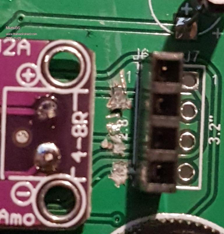
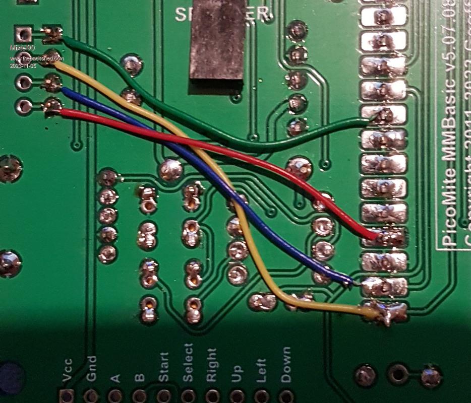
The display and touch are using SPI. On the standard construction the SD card is also connected to this. We can transfer it to different pins. We'll use GP16, GP17 and GP18 as the SD card doesn't need hardware SPI. In order to split the SD card SPI from the display and touch: Using a sharp knife or, possibly a very fine Dremel tool, you need to identify and cut the following three tracks. They are all between the PAM8302A and the connector J6 so it's a bit fiddly. The one just underneath the figure 1 The one under the figure 2 of 2.8 The bottom one Don't cut the track between the 2 and the bottom track. If you there's a work-around. :)  Pins 2,3 and 4 of J6 and J7 should now be isolated from pins 5, 6 and 9 of the PicoMite. Now, on the back of the PCB, fit three wire links: J6 pin 2 - GP16 (pin 21 - yellow J6 pin 3 - GP17 (pin 22 - blue) J6 pin 4 - GP18 (pin 24 - red) If you cut the track mentioned above that's in the way (like I did) you'll need an additional link: J6 pin 1 - GP22 (pin 29 - green)  Now the software has to be changed to work with the new arrangement. Change OPTION SDCARD to the following: OPTION SDCARD GP22, GP18, GP16, GP17 This keeps the original SD_CS as GP22 and moves SD_CLK to GP18, SD_MOSI to GP16 and SD_MISO to GP17. I've had this mod working today. Edited 2023-11-05 05:13 by Mixtel90 Mick Zilog Inside! nascom.info for Nascom & Gemini Preliminary MMBasic docs & my PCB designs |
||||
bigmik Guru Joined: 20/06/2011 Location: AustraliaPosts: 2914 |
Hi Mick, All, Ohhh No, our lovely board has been attacked with an axe already..  If someone wanted to change the SD card as suggested AND (a big AND) they were using a 3.2” TFT, then the cuts are simpler, just drill out the pads on the unused 2.8” connector (J6). You only need to use a 4mm drill and drill away the partial pad on the underside of the PCB. (Only the 3 pads that need to be relocated). Then run the jumpers to J7 (instead of J6 as shown above). This will be ONLY if a 3.2” TFT is used. Kind Regards, Mick (the big one) . Edited 2023-11-05 09:32 by bigmik Mick's uMite Stuff can be found >>> HERE (Kindly hosted by Dontronics) <<< |
||||
| Mixtel90 Guru Joined: 05/10/2019 Location: United KingdomPosts: 6786 |
Sorry, Mick, I can't resist a PCB trace when I have a knife in my paws! Yeah, that would be far easier. It's also easy if you haven't fitted the Pico as the traces are very easy to get to under there. I considered using SP2 on GP26, GP27 & GP28 but I don't think the SD card is ever driven using hardware SPI, the pins are used in software mode anyway. I figured it would be better to leave those pins available as they are of more use for expansion. Just a thought. If you ever do a new version it might be handy to have Reset on the expansion port. That way an I2C expander could be used more successfully. Cheers, Mick (the one with the green hat) Mick Zilog Inside! nascom.info for Nascom & Gemini Preliminary MMBasic docs & my PCB designs |
||||
| thwill Guru Joined: 16/09/2019 Location: United KingdomPosts: 4037 |
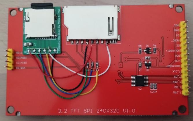
My Game*Mite display is now retrofitted with a push-push uSD card adapter, PCB by @bigmik  "Yes", the soldering is a bit ropey and I should probably shift the adapter down the board by ~2mm to reduce the risk of it being accidentally being pushed, but that's titivating for another day. Feeling well pleased. Thanks Mick. Best wishes, Tom Game*Mite, CMM2 Welcome Tape, Creaky old text adventures |
||||
| lizby Guru Joined: 17/05/2016 Location: United StatesPosts: 3150 |
What is the advantage to this mod? PicoMite, Armmite F4, SensorKits, MMBasic Hardware, Games, etc. on fruitoftheshed |
||||
| thwill Guru Joined: 16/09/2019 Location: United KingdomPosts: 4037 |
I find the full-size SD card/adapter liable to being knocked or snagged, plus aesthetically I think it looks better with the card fully concealed beneath the display. In addition I've wired it to remove the three "unnecessary" series resistors from the SD card lines whilst adding an additional 100nF decoupling capacitor. YMMV, Tom Edited 2023-11-20 00:31 by thwill Game*Mite, CMM2 Welcome Tape, Creaky old text adventures |
||||
| Mixtel90 Guru Joined: 05/10/2019 Location: United KingdomPosts: 6786 |
I like it. :) I like to see hacked PCBs, of course, so maybe I'm a little biased? Mick Zilog Inside! nascom.info for Nascom & Gemini Preliminary MMBasic docs & my PCB designs |
||||
bigmik Guru Joined: 20/06/2011 Location: AustraliaPosts: 2914 |
Good work Tom, If we ever do a new version we should provide the pads as an option to accommodate this pcb. I was surprised that an adapter like this one doesn’t seem to exist with a push-push type uSD socket, they all seem to use the cheaper push-pull type. Regards, Mick Edited 2023-11-20 08:51 by bigmik Mick's uMite Stuff can be found >>> HERE (Kindly hosted by Dontronics) <<< |
||||
| thwill Guru Joined: 16/09/2019 Location: United KingdomPosts: 4037 |
Thanks Mick, and you  . .Or add the socket footprint directly to the PCB. Though as a module there is at least one non push-pull version that would fit on the same 6-pin footprint. I have a list of relatively minor tweaks we could make for a v1.4 PCB, but at the moment I'm more interested in giving the software a slap of makeup before I make a YouTube video and try to push it out to a wider audience. I think this might be one Mick, I found it after we'd both already ordered your PCBs  : :https://www.aliexpress.com/item/32787519908.html Best wishes, Tom Edited 2023-11-20 20:41 by thwill Game*Mite, CMM2 Welcome Tape, Creaky old text adventures |
||||
| matherp Guru Joined: 11/12/2012 Location: United KingdomPosts: 9115 |
Tom Please can you explain your approach to a standard I/F for multiple types of controller and I will see if I can make the Wii Classic easily compatible. Thanks |
||||
| thwill Guru Joined: 16/09/2019 Location: United KingdomPosts: 4037 |
Thank you for reaching out Peter, I've started a new thread: https://www.thebackshed.com/forum/ViewTopic.php?PID=212744 IFF your PicoMite{VGA} implementation is a copy & paste from the CMM2 then I would expect my existing Wii controller subs would work, but I believe that due to limitations on number of tokens they may need to be rewritten to use new keyword arrangements. Best wishes, Tom Edited 2023-11-21 10:37 by thwill Game*Mite, CMM2 Welcome Tape, Creaky old text adventures |
||||
| Turbo46 Guru Joined: 24/12/2017 Location: AustraliaPosts: 1611 |
In a different post: The Manual must also change? Bill Keep safe. Live long and prosper. |
||||
| thwill Guru Joined: 16/09/2019 Location: United KingdomPosts: 4037 |
Yes, no rest for the virtuous. Tom Game*Mite, CMM2 Welcome Tape, Creaky old text adventures |
||||
| thwill Guru Joined: 16/09/2019 Location: United KingdomPosts: 4037 |
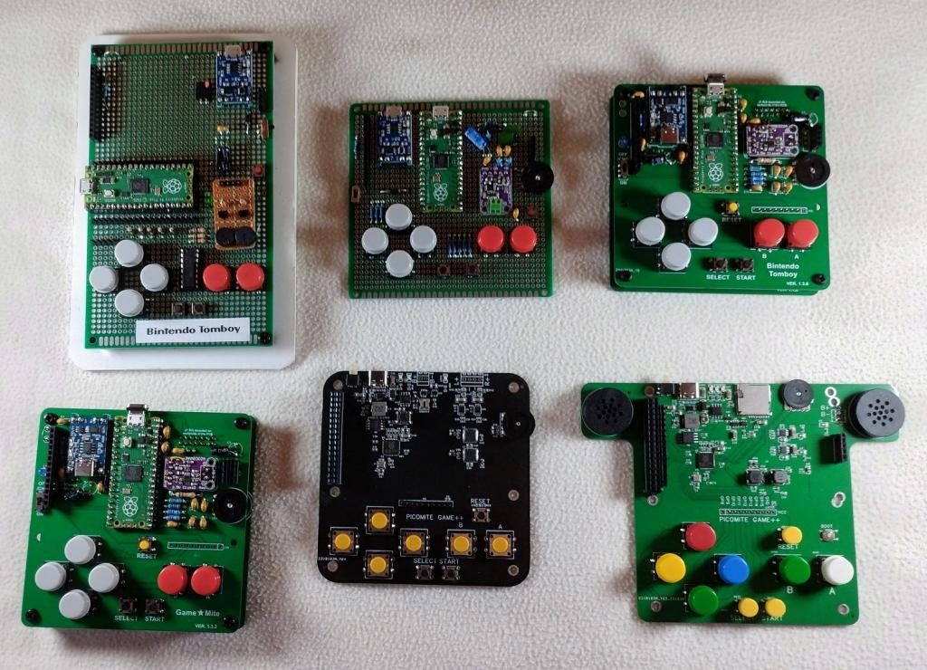
Hi folks, At this time of the year it's nice for family together and thanks to a generous gift from Peter they can:  Pity about the poor quality photo. Top Left: Original prototype Top Middle: 2nd prototype Top Right: Pre-release Bottom Left: Release v1.3.2 PCB Bottom Middle: Peter's 2nd (?) prototype Bottom Right: Peter's final (?) version Thanks again Peter. Best wishes, Tom Game*Mite, CMM2 Welcome Tape, Creaky old text adventures |
||||
| Mixtel90 Guru Joined: 05/10/2019 Location: United KingdomPosts: 6786 |
What a lovely collection. :) Mick Zilog Inside! nascom.info for Nascom & Gemini Preliminary MMBasic docs & my PCB designs |
||||
| thwill Guru Joined: 16/09/2019 Location: United KingdomPosts: 4037 |
Hi folks, I'm putting the finishing touches to v1.2 of the Game*Mite software and need to decide whether to bump up the default MODBUFF from 128K to (for example) 192K. For the moment this is solely required to support PETSCII Robots ... unless Martin still thinks he can shrink that games MOD sizes ? Thoughts ? Best wishes, Tom Game*Mite, CMM2 Welcome Tape, Creaky old text adventures |
||||
| Volhout Guru Joined: 05/03/2018 Location: NetherlandsPosts: 4232 |
Tom, I'll leave this up to Martin_H to answer about the 128k. Note: the MODBUFF can be any multiple of 4k, and for the largeste Petscii sound file, 180k is working, not 192k. Volhout PicomiteVGA PETSCII ROBOTS |
||||