|

|
Forum Index : Microcontroller and PC projects : Getting the best out of Pico ADC
| Author | Message | ||||
| stanleyella Guru Joined: 25/06/2022 Location: United KingdomPosts: 2129 |
 |
||||
| Mixtel90 Guru Joined: 05/10/2019 Location: United KingdomPosts: 6798 |
Since I've no LCD displays set up I can't test any of these. Sorry, Stan, I thought you were trying to convert the code that Jim has run on a ILI9341 without doing anything to it. If it's different code then all bets are off. :) Mick Zilog Inside! nascom.info for Nascom & Gemini Preliminary MMBasic docs & my PCB designs |
||||
| NPHighview Senior Member Joined: 02/09/2020 Location: United StatesPosts: 200 |
This approach, in general, should work very nicely on the Colour Maximite attached to a VGA display. The code, with very few modifications, works great on a Waveshare Pico-Eval-Board (mainly changing i/o pins). By the way, I've been playing with alternate, adaptive triggering algorithms and this one seems to be working nicely (more testing will tell): Function find_trigger(a) Local mean = Math(MEAN sample()) Select Case a Case Trig_Down For c = 0 To Hres-1 If sample(c) > mean+0.1 And sample(c+1) < mean+0.2 Then find_trigger = c : Exit Function Next find_trigger = -1 : Exit Function Case Trig_Up For c = 0 To Hres-1 If sample(c+1) > mean+0.1 And sample(c) < mean+0.2 Then find_trigger = c : Exit Function Next find_trigger = -1 : Exit Function Case Else find_trigger = 0 : Exit Function End Select End Function All I did was calculate the mean value for the array full of ADC values, then find the point at which the waveform rises through it or falls through it (based on trigger direction selection), and that's the trigger point. Not sure it'll work on slowly varying signals, but that kind of triggering is problematic on my actual, physical Tektronix scope. Once again, Peter's excellent math library comes to the rescue! Live in the Future. It's Just Starting Now! |
||||
| stanleyella Guru Joined: 25/06/2022 Location: United KingdomPosts: 2129 |
NPH- interesting. Math is new to me. I tried math min for trigger but it's new and I don't understand. Changed vars to integer.minval%=MATH(MIN scaledsamples%(),c%) -- c%is lowest value in scaledsamples% ??? error message c%= > RUN 0 0 0 0 0 79 0 6 0 0 164 [38] Line x%,scaledsamples%(x%+c%),x%+1,scaledsamples%(x%+1+c%),,RGB(magenta) 'draw new sample from ) Error : Index out of bounds > code do adc start samples!() 'get new samples math scale samples!(),79,scaledsamples%()'scale to 80 pixel height minval%=MATH(MIN scaledsamples%(),c%) print c% do:If scaledsamples%(c%+1) > scaledsamples%(c%) then if scaledsamples%(c%+2) > scaledsamples%(c%+1) then exit do inc c%:loop while c%<99 FRAMEBUFFER COPY L,F for x%=0 to 158 'screen width line x%,scaledsamples%(x%+c%),x%+1,scaledsamples%(x%+1+c%),,rgb(magenta) 'draw new sample from sample(c%) next x% FRAMEBUFFER COPY F,N loop |
||||
| Mixtel90 Guru Joined: 05/10/2019 Location: United KingdomPosts: 6798 |
If you want to show code, Stan, surround it with {CODE} and {/CODE} but with square brackets rather than curly. It will keep your formatting then. The codes themselves don't display. e.g. 'this is a comment 'this is another for j=1 to 5 for i = 5 to 10 print j*i next next Mick Zilog Inside! nascom.info for Nascom & Gemini Preliminary MMBasic docs & my PCB designs |
||||
| stanleyella Guru Joined: 25/06/2022 Location: United KingdomPosts: 2129 |
ok Mick. I just copy from mmedit. The manual MATH(MIN a(), [index%]) is math scale samples!(),79,scaledsamples%()'scale to 80 pixel height minval%=MATH(MIN scaledsamples%(),c%) convert ad samples!() to scaledsamples%() then find minval% and is c% the array pointer to lowest value in array? |
||||
| phil99 Guru Joined: 11/02/2018 Location: AustraliaPosts: 2137 |
From your output the last (tenth, counting from 0) value of c% was 164, so [38] Line x%,scaledsamples%(x%+c%),x%+1,scaledsamples%(x%+1+c%),,RGB(magenta) 'draw new sample from ) Error : Index out of bounds means x%+1+c% (10 + 1 + 164 = 175) is greater than the size of the array. The array needs to be at least double the screen width. Dim scaledsamples%(mm.hres * 2 + 1) Edit You could then use MEMORY COPY to start copying from scaledsamples%() at index c% to another array equal to mm.hres. Then you just plot from the start of the new array. Dim OutputArray%(mm.hres +1) offset% = Peek(varaddr scaledsamples%()) output% = Peek(varaddr OutputArray%()) Memory Copy INTEGER offset% + c%*8, output%, HRes Depending on how the code for MEMORY COPY works it might be possible to copy back to the start of scaledsamples%(), no extra array needed. Edit 2 TESTED - it works! offset% = Peek(varaddr scaledsamples%()) Memory Copy INTEGER offset% + c%*8, offset%, MM.HRes Then you just plot from the start of scaledsamples%(). . Edited 2023-08-17 14:06 by phil99 |
||||
| stanleyella Guru Joined: 25/06/2022 Location: United KingdomPosts: 2129 |
Thankyou @phil99. I've not used peek yet... er...seemed so 80's or picaxe :) I guess my trigger doesn't always find a trigger so the index overflows. First time I used math min and not sure if [index] was pointer to lowest value element. do:If scaledsamples%(c%+1) > scaledsamples%(c%) then if scaledsamples%(c%+2) > scaledsamples%(c%+1) then exit do inc c%:loop while c%<99 |
||||
| phil99 Guru Joined: 11/02/2018 Location: AustraliaPosts: 2137 |
For those who do want to see the rise and fall of square waves I think these small mods to the last two Subs should do it. Not tested, it may be necessary to increase the size of sample!() by 1 if you get "Error: Index out of bounds" Sub Scale_Samples Memory copy FLOAT addr.sample + trigger*8, addr.buffer, Hres Math Scale buffer!(), V.Scale(Vselect), buffer!() ' Scale samples to fit vertically Math Add buffer!(), V.Offset(Vselect), buffer!() ' Offset to bottom of screen (positive is up) Memory copy FLOAT addr.buffer + 8, addr.sample, Hres 'Back copy samples with 1 pixel offset for vertical edges End Sub Sub Update_Display FRAMEBUFFER COPY L, F ' FRAMEBUFFER WRITE F : Pixel Horizontal(), buffer!(), Signal FRAMEBUFFER WRITE F : Line Horizontal(), buffer!(), Horizontal(), sample!(),, Signal FRAMEBUFFER COPY F,N End Sub Edited 2023-08-17 23:15 by phil99 |
||||
| Mixtel90 Guru Joined: 05/10/2019 Location: United KingdomPosts: 6798 |
As the rising and falling edges of a PWM output are so fast on the Pico you probably shouldn't be able to see them. Probably not with a 500kHz ADC sampling rate anyway. :) Those edges are hardware generated on the chip and aren't related to the speed of MMBasic. Mick Zilog Inside! nascom.info for Nascom & Gemini Preliminary MMBasic docs & my PCB designs |
||||
| NPHighview Senior Member Joined: 02/09/2020 Location: United StatesPosts: 200 |
stanleyella: Along the way, our collective mind set the signal buffer to twice the display width and searched for the trigger only up to the display width. This way, the memory copy only starts at the trigger and never overruns the signal buffer. phill99: I like this! I anticipated having to declare a third (or fourth, counting Horizontal()) array, and re-using the sample() array is great!. I haven't tried it yet, but it sure looks like it'll work, except when the trigger is right at the boundary between the first and second halves of the signal array. Maybe only searching for a trigger up to one less than half the sample() width would alleviate this concern... Edited 2023-08-18 00:27 by NPHighview Live in the Future. It's Just Starting Now! |
||||
| stanleyella Guru Joined: 25/06/2022 Location: United KingdomPosts: 2129 |
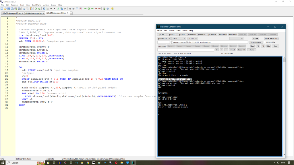
I removed trigger and used plot instead of line but just get a row of samples with flickering pixels for the rest? SetPin GP18,pwm1A 'this optional test signal comment out PWM 1,10000,30 'square wave ,this optional test signal comment out dim c%,x%,samples!(320) SETPIN (31), AIn adc open 500000,1 'samples per second FRAMEBUFFER CREATE F FRAMEBUFFER LAYER L FRAMEBUFFER WRITE L line 79,0,79,79,,rgb(green) line 0,39,159,39,,rgb(green) FRAMEBUFFER WRITE F do adc start samples!() 'get new samples math scale samples!(),79,samples!()'scale to 80 pixel height FRAMEBUFFER COPY L,F for x%=0 to 159 'screen width pixel x%,samples!(x%),rgb(magenta) 'plot new sample next x% FRAMEBUFFER COPY F,N loop |
||||
| stanleyella Guru Joined: 25/06/2022 Location: United KingdomPosts: 2129 |
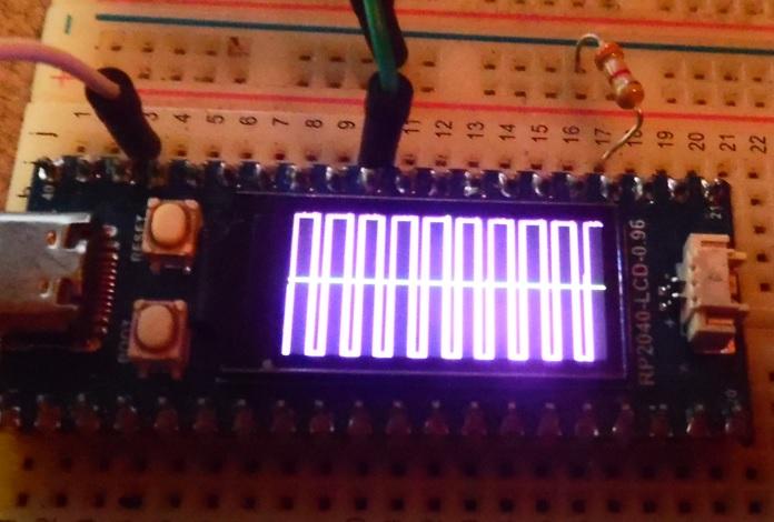
Hi Mick. er.. I can see them with join the samples with lines. Lines take more time than pixels and my prob is not realizing how fast everything is. My crude trigger I can't find how to improve but a 9999Hz pwm doesn't move much. It was never meant to be a real scope just a-d idea but I've learnt lots of new mmbasic stuff from this thread. As mentioned, could be handy for breadboard testing... if no real scope handy. could it be used for i2c,spi,pwm,serial testing. if the sampling rate was changed? All input would be 3.3V. Maybe leave sampling at 500000 and if storing to array then pad out horizontal for lower frequencies for display, just a thought. 30KHz pwm 30%  |
||||
| Mixtel90 Guru Joined: 05/10/2019 Location: United KingdomPosts: 6798 |
Joining the samples with vertical lines is deceptive. The line thickness can represent several hundred microseconds on the display (it will actually depend on what your horizontal scale factor is). In actual fact the rise and fall times may only be a few microseconds. However, with edges that fast you can't see them on the display unless you make the horizontal zoom factor very big (only show one edge of the square wave, for example). Whatever you do on such a small display will be a compromise. You can see this effect very nicely on an analogue scope. You won't see the rising and falling edges until you increase the brightness as they are too fast for the electron beam to put sufficient energy into the phosphor of the tube. Mick Zilog Inside! nascom.info for Nascom & Gemini Preliminary MMBasic docs & my PCB designs |
||||
| stanleyella Guru Joined: 25/06/2022 Location: United KingdomPosts: 2129 |
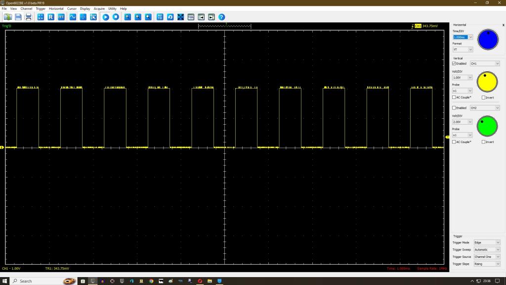
I saw an Asteroids board connected to a xy analogue scope in the 70's. wouldn't work without the phosphor on a sampling scope. my cheap hantek usb scope shows vertical trace for digital signals  |
||||
| phil99 Guru Joined: 11/02/2018 Location: AustraliaPosts: 2137 |
I like that idea of different colours for overlapping pixel and line displays. I think this will give a similar effect on NPHighview's scope. Sub Scale_Samples Memory copy FLOAT addr.sample + trigger*8, addr.buffer, Hres Math Scale buffer!(), V.Scale(Vselect), buffer!() ' Scale samples to fit vertically Math Add buffer!(), V.Offset(Vselect), buffer!() ' Offset to bottom of screen (positive is up) Memory copy FLOAT addr.buffer + 8, addr.sample, Hres 'Back copy samples with 1 pixel offset for vertical edges End Sub Sub Update_Display FRAMEBUFFER COPY L, F FRAMEBUFFER WRITE F : Line Horizontal(), buffer!(), Horizontal(), sample!(),, RGB(64,64,64) FRAMEBUFFER WRITE F : Pixel Horizontal(), buffer!(), Signal FRAMEBUFFER COPY F,N End Sub Edit Tested the idea on my offering on page 3 and it does look better. 'plot trace Line x, samples(x+TC)-V.offset, x, samples(x+1+TC)-V.offset,, RGB(64,64,64) Pixel x, samples(x+TC)-V.offset, RGB(255,128,0) Edited 2023-08-18 18:36 by phil99 |
||||
| stanleyella Guru Joined: 25/06/2022 Location: United KingdomPosts: 2129 |
NPH and phill99 scope no keyboard needed would be nice, no hardware. Software selection of options. Can't I measure the input freq then set up best display auto? probably but others code gets more complex.. just lots of it. subs are so distracting trying to follow the flow. edit Not moaning just sub everything. Guess it doesn't slow code down much like 8bit. Edited 2023-08-19 07:46 by stanleyella |
||||
| NPHighview Senior Member Joined: 02/09/2020 Location: United StatesPosts: 200 |
Hi - I've got three momentary-contact, pushbutton switches, one to cycle through time / ADC frequency, the next to select triggering, the the last to cycle through voltage ranges. See my Handle_Pushbuttons subroutine. Live in the Future. It's Just Starting Now! |
||||
| Mixtel90 Guru Joined: 05/10/2019 Location: United KingdomPosts: 6798 |
That's very nice. :) Mick Zilog Inside! nascom.info for Nascom & Gemini Preliminary MMBasic docs & my PCB designs |
||||
| Mixtel90 Guru Joined: 05/10/2019 Location: United KingdomPosts: 6798 |
In a word, no. Not if you want a scope anyway. You don't know in advance how many cycles of the waveform the user wants to see, or even if they want to see just the top or just the bottom of it. You don't know the frequency, voltage, DC offset or shape of the waveform. I have one of those little scopes with a single button on it which is used for absolutely everything. Believe me, being minimalist on controls can get very awkward indeed. You can make something that displays *something* when you connect it, but it may as well be an auto-ranging AC voltmeter for all the good it will be. Mick Zilog Inside! nascom.info for Nascom & Gemini Preliminary MMBasic docs & my PCB designs |
||||