
|

|
Forum Index : Microcontroller and PC projects : PicoMite: driving a small speaker
| Author | Message | ||||
| Turbo46 Guru Joined: 24/12/2017 Location: AustraliaPosts: 1611 |
 Isn't there also a module that include battery management? Bill Keep safe. Live long and prosper. |
||||
| thwill Guru Joined: 16/09/2019 Location: United KingdomPosts: 4047 |
Thanks Bill, Looks "proper" enough to me. This I don't "get". Running on battery, everything except the controller circuit (pin 36, 3V3) has exactly the same supply, the battery via the schotky diode (SW10), power switch (SW10) and decoupling capacitors ultimately connected to the Pico (pin39, VSYS), LCD and amplifier. OK, but like supplying the amplifier from a completely independent supply it is easy to do and potentially educational. Best wishes, Tom Game*Mite, CMM2 Welcome Tape, Creaky old text adventures |
||||
| Mixtel90 Guru Joined: 05/10/2019 Location: United KingdomPosts: 6812 |
Beware - any devices using a linear regulator have an input voltage problem if you are using batteries. You need 3v3 and the linear reg will need around 0.2V across it for a LDO, so that's 3V5 in. Lithium are only 3V7 to start off with (once charged). You may need two batteries. I'd need to check this. Mick Zilog Inside! nascom.info for Nascom & Gemini Preliminary MMBasic docs & my PCB designs |
||||
| Volhout Guru Joined: 05/03/2018 Location: NetherlandsPosts: 4253 |
Hi Tom, Mick, I would power the pico from it's switching regulator, not from a linear regulator. The onboard switcher can handle power, peripherals, wide range battery voltages. I would power the audio amplifier (PAM8403) directly from the LiPo (3.7V). It is designed for single cell (3.7V) use. To limit the noise in the audio (caused by the onboard switching regulator) we need to add something like Turbo is working on with the diodes or LED's. This is the part that needs some engineering. The solution with the transistor is nice, but many more components (since it needs a quiet 3.3V, e-caps, etc) where diodes/LED's do not. Volhout Edited 2023-03-31 21:07 by Volhout PicomiteVGA PETSCII ROBOTS |
||||
| Turbo46 Guru Joined: 24/12/2017 Location: AustraliaPosts: 1611 |
The resistor and the two capacitors will filter or decouple the supply and hopefully remove most of the noise produced by the Pico. so switching on that supply using the transistor should produce a PWM signal that has none or very little noise superimposed on it. The electrolytic will remove most of the lower frequency noise while the 0.1uF will cope with the higher frequencies. Standard electrolytics have an effective series resistance (ESR) which does limit their high frequency response (tantalims are better). Not sure if that answers what you don't get. Bill Keep safe. Live long and prosper. |
||||
| thwill Guru Joined: 16/09/2019 Location: United KingdomPosts: 4047 |
I don't imagine this will help, but can't hurt: 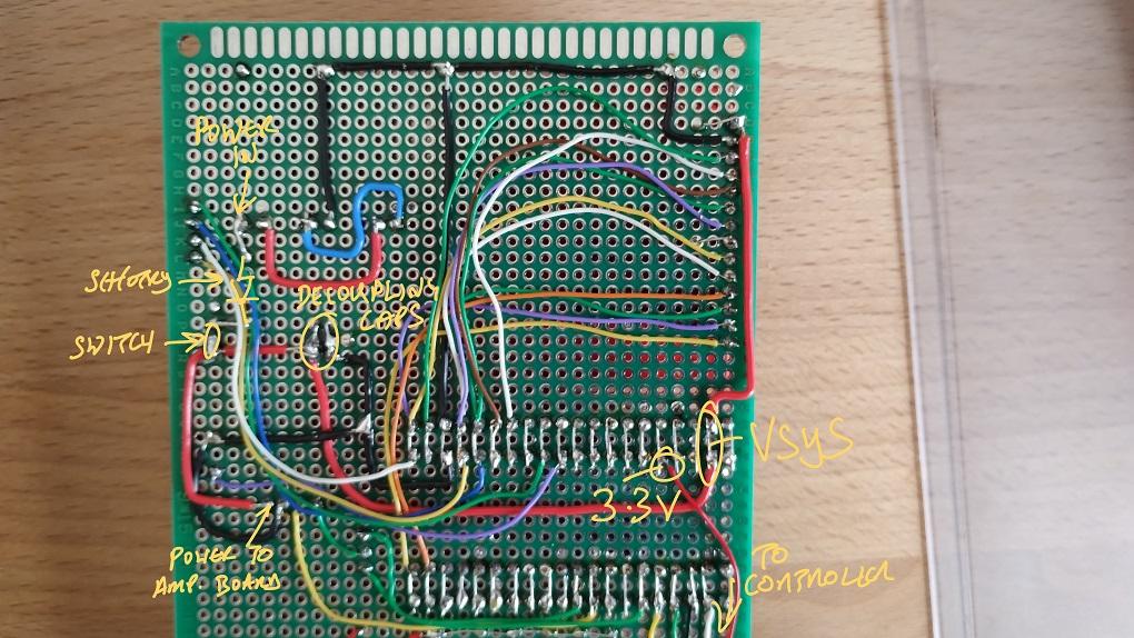 I note now that the + line to the "amp board" is coming directly off the switch, not after the decoupling capacitors, but there is another pair of decoupling capacitors on the "amp board". Best wishes, Tom Game*Mite, CMM2 Welcome Tape, Creaky old text adventures |
||||
| mozzie Regular Member Joined: 15/06/2020 Location: AustraliaPosts: 68 |
G'day Tom, sorry if this is adding to the overload... Can I suggest trying the larger speaker you have, but cut a hole in a piece of cardboard or cardboard box and mount it through it, doesn't have to be anything fancy  I am using the 40mm version of the speaker you have and without a baffle there is not a lot of volume, more noise. I am using the 40mm version of the speaker you have and without a baffle there is not a lot of volume, more noise.By the time you have decent volume, the amp is way into overload and adding noises / buzzing of its own  Can I also suggest trying TRIANGLE "t" instead of SINE "s" in play sound, it adds a lot of harmonics and through a small speaker sounds a lot louder. (richer?)  Hope this helps. Also now have Vivaldi's "Spring" playing and through the 6" speakers I have out here it sounds nice, that piece of software of yours is very good  Regards, Lyle. |
||||
| Turbo46 Guru Joined: 24/12/2017 Location: AustraliaPosts: 1611 |
Hang on a minute. You said earlier that the 10R in series with the amplifier was causing problems. If that was in series with the amp why weren't the capacitors in the circuit. Maybe I'm missing something but I'm trying to keep up.  Bill Keep safe. Live long and prosper. |
||||
| mozzie Regular Member Joined: 15/06/2020 Location: AustraliaPosts: 68 |
In the world of analog there is no such thing as too much supply decoupling, In mixed analog / digital you need more than that again  What you have there should be ok. If I remember correctly "Power in" is direct from the battery. |
||||
| Turbo46 Guru Joined: 24/12/2017 Location: AustraliaPosts: 1611 |
Batteries also have ESR so the supply from them has the potential to contain noise that is caused by the devices that they supply. As you say: "there is no such thing as too much supply decoupling". Bill Keep safe. Live long and prosper. |
||||
| thwill Guru Joined: 16/09/2019 Location: United KingdomPosts: 4047 |
EDIT: I think this was me failing to distinguish arse from elbow, this is what it looks like flattened out: 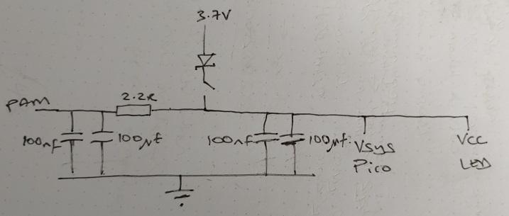 The amp board (infact the whole audio train) is a breakout that amongst other things includes the (now 2.2R) resistor another pair of decoupling caps and the PAM module. One of the things I got right with this build is I didn't solder any audio to the main board, instead there is a 4 pin header taking power, earth and two sound channels. You and me both  . .<Head explodes>  . .Everyone note that's the polite way of saying I should stick to programming  . .Thanks, though probably more thanks to Vivaldi, my wife for transcribing it and Peter for fixing the issues with PLAY SOUND. Best wishes, Tom Edited 2023-03-31 23:20 by thwill Game*Mite, CMM2 Welcome Tape, Creaky old text adventures |
||||
| Volhout Guru Joined: 05/03/2018 Location: NetherlandsPosts: 4253 |
@Tom, The small speaker will most likely not give you the performance you desire. Minimally you will have to give them an acoustic chamber in some form. I achieved significan improvement by placing my small speakers in a toilet paper carton tube. But I assume your handheld game housing could also work as such, as long as it is more or less a closed system. The circuit itself is not very critical if you only want computer sounds up to few kHz. This is my setup without the carton tubes (they are visible at the top edge of the photo. Bottom: the 1S LiPo (3.7V), the PAM8403 with (not visible) volume control. The 2 speakers (1.8"), to the right my breadboard PicomIte. 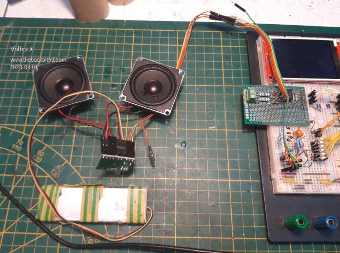 In my setup I have used the picomite switchmode powersupply, and that generates quite a lot of noise and buzz. I have minimized the buzzing by clipping the PWM signal in a diode clipper. For those who wonder why double diodes and AC coupling. Using a single diode of LED gave huge non-linearity. 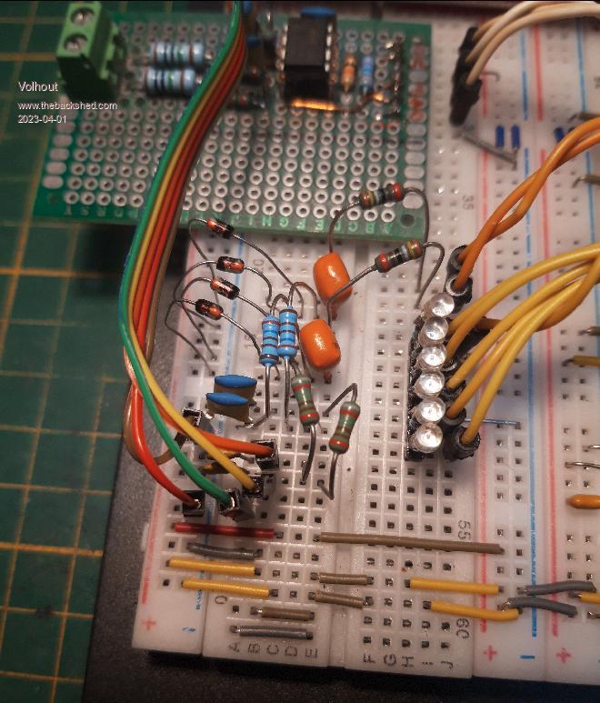 With the little speakers the sound was so-so (missing all low frequencies). But with a decent speaker... the Dires Straits where very enjoyable (despite the 5kHz rollo-off of this filter). I use the Dire Straits live album because it has so much dynamics, from very silent and mellow sounds, up to roaring guitar. 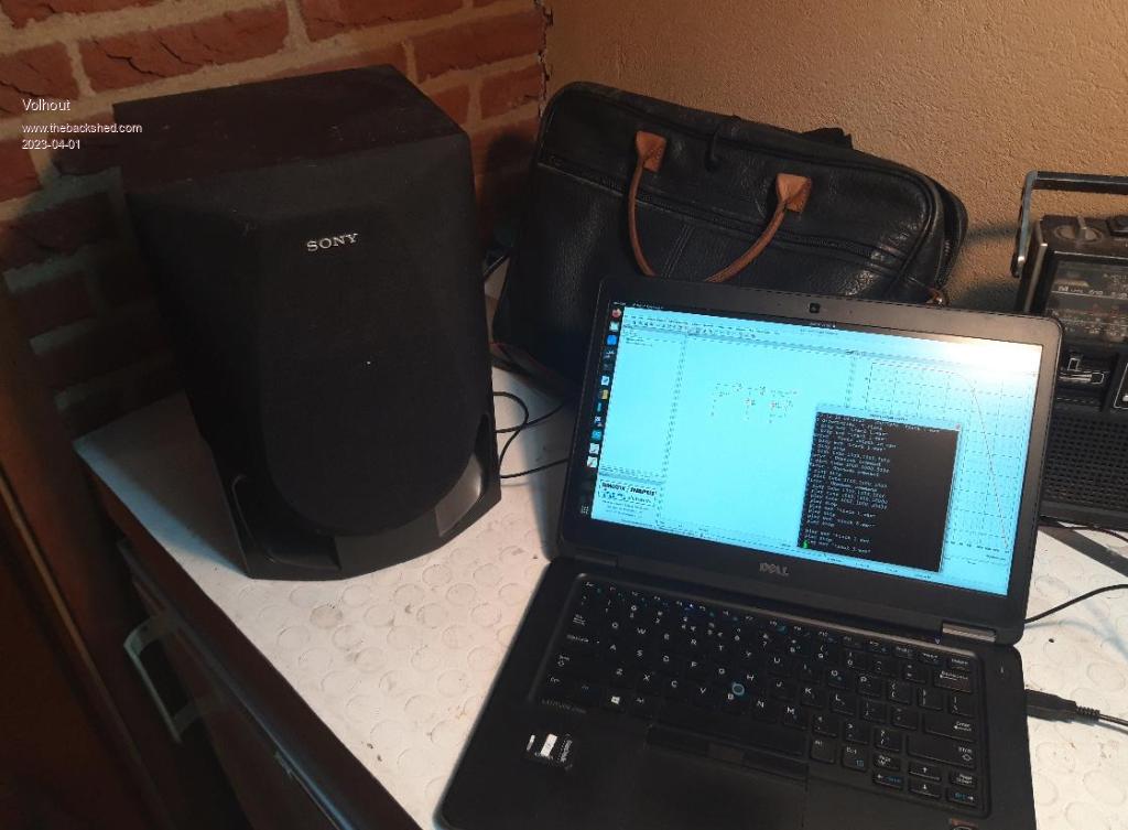 This is the filter I used (1 per channel L and R). I guess, the diodes and the 330 ohm resistor and 2.2uF capacitor can be removed, when you use a linear regulator for the picomite power. It should be more than adequate for the game sounds, and has 30dB rejection at 44kHz with NO INDUCTORS... 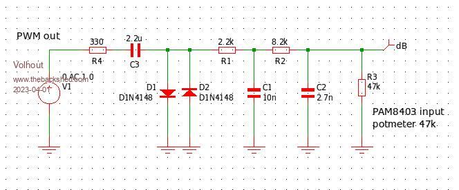 The filter can be made in SMD, so it will only be sugar cube size PCB (for stereo). But honestly...Tom... the essence is in the small speakers, and how to get them accousic best coupled to the user. The PAM8403 is amazing, how much sound you get from a single lipo when using a decent speaker... Volhout P.S. for those who notice the constant noise when volume is turned up high: this is becuase the audio output of the PicoMite is only 10 bits. Now adays people are used to 16dB or more audio DAC's and a -90...-100dB noise floor. In this picomite we only have -55dB. Edited 2023-04-01 06:19 by Volhout PicomiteVGA PETSCII ROBOTS |
||||
| thwill Guru Joined: 16/09/2019 Location: United KingdomPosts: 4047 |
Thanks Volhout, I feel like an idiot for asking what are no doubt questions with obvious answers, but better that than an ignoramus who is too proud: 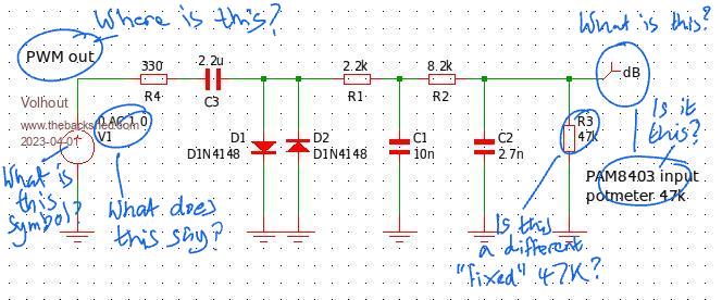 Separately in my own investigation I found that when using a completely independent power supply for the amplifier, the speaker still whined/whistled but no longer pulsed in time with the heartbeat LED. Best wishes, Tom Edited 2023-04-01 08:48 by thwill Game*Mite, CMM2 Welcome Tape, Creaky old text adventures |
||||
| Turbo46 Guru Joined: 24/12/2017 Location: AustraliaPosts: 1611 |
Thanks Tom, your hand drawn schematic is how I think the circuit should be. If there are more bypassing capacitors on the PAM then you can't have too much..... @Volhout, Every thing you say is perfectly valid except: Remember, he was sort of happy with the sound of the buzzers. Moving to an audio amplifier highlighted the problem of the noise. He wants to make a compact unit that will play games and produce sounds to accompany them. With over 0.1% distortion the PAM is hardly HiFi. It's frequency response begins to roll off around 20kHz so 44.1kHz will be quite attenuated by the amplifier alone. The filter is not the only thing affecting the frequency response. He wants a small speaker to suit the nature of the device. Yes, an enclosure does make a world of difference but that is not practical for this device, if Tom decides to use a case then that should help. Tom, If I am talking out of my backside then please correct me. HE NEEDS TO ADDRESS THE NOISE FIRST. Bill Keep safe. Live long and prosper. |
||||
| Turbo46 Guru Joined: 24/12/2017 Location: AustraliaPosts: 1611 |
That suggests that the whine/whistle is coming in via the audio input. That should be improved by adding the transistor circuit or another form of clipping. The pulsing caused be the heartbeat LED must be coming via the power supply. Pardon my ignorance here, but cannot the heartbeat LED be disabled? Bill Keep safe. Live long and prosper. |
||||
| hitsware2 Guru Joined: 03/08/2019 Location: United StatesPosts: 713 |
Or ( in many cases ) the result of 2 switchers heterodyning ..... my site |
||||
| Turbo46 Guru Joined: 24/12/2017 Location: AustraliaPosts: 1611 |
Possibly, But "using a completely independent power supply for the amplifier,"? Bill Keep safe. Live long and prosper. |
||||
| phil99 Guru Joined: 11/02/2018 Location: AustraliaPosts: 2140 |
The heartbeat LED can be disabled but it is just highlighting the problem. As it switches on and off it is loading / unloading the regulator so its noise is changing. OPTION HEARTBEAT OFF will make it less obvious. In Toms annotated circuit:- Where is this? = PWM out = Pico audio out pin What does this say? = DAC01 = digital to analogue converter 1 What is this symbol? = signal source (above three are all the same thing) Is this a "different" 47k? = no it is the PAM8403 input potentiometer. What it this? = dB = measurement point (in decibells) for the circuit simulator - not part of the circuit Is it this? = no |
||||
| Turbo46 Guru Joined: 24/12/2017 Location: AustraliaPosts: 1611 |
True. I'm disappointed that the Pico's supply is that poor that a LED switching on and off can produce that problem and also that the decoupling cannot improve it. I would still like to further investigate the affect of disabling the internal buck/boost regulator. Bill Keep safe. Live long and prosper. |
||||
| mozzie Regular Member Joined: 15/06/2020 Location: AustraliaPosts: 68 |
G'day all, Sorry if I've caused any confusion here, maybe a little further explanation.. I have set up a circuit very similar to Tom's, however I can't find a 27mm speaker (here somewhere...) so am using its 40mm bigger brother. Also my PAM amp board is slightly different. The concern with the setup was the open 27mm speaker, most of the output from "LaserCycleMusic" is relatively low frequency sine waves, and to get any decent output from even the 40mm speaker means having the "volume" turned up a long way. This accentuates the noise problem as the 27mm speaker is quite good at reproducing this even open. On top of this is the PAM also being over-driven to get decent volume and adding the usual horrid artifacts that class D amps produce if over-driven. Basically if it sounds good into a larger speaker then that means the amp / filter circuit is ok and the problem is the speaker. Previous experience shows that the 40mm speaker is a lot more efficient and this is even more evident at lower frequencies, maybe it can be squeezed into the TomBoy? Changing the SINE "s" in play sound to TRIANGLE "t" also makes a big difference as it has a lot more harmonic content but it sounds different, a lot more like a computer game in my mind  As others have found, the PSU in the Pico is very noisy and gets worse as it goes from buck to boost mode so this needs to be sorted out, however it is very good with a battery supply so if we can collectively get this to work I think we will be on a winner  Regards, Lyle. |
||||