
|

|
Forum Index : Electronics : 12v Dc timer module SILCON CHIP MAG
| Author | Message | ||||
| larny Guru Joined: 31/10/2011 Location: AustraliaPosts: 346 |
I need a photo of both sides of the PCB please. Len 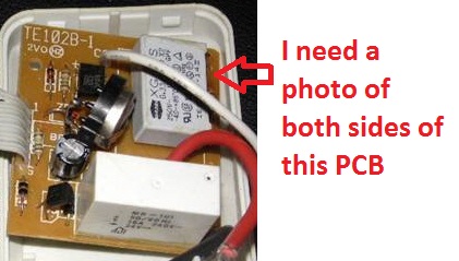
|
||||
| larny Guru Joined: 31/10/2011 Location: AustraliaPosts: 346 |
Here is a photo of my meter, is similar to yours except that yours has a transistor test function. I have several meters, this one is the simplest. You should measure the voltages with the DCV range. Start on the 200 Volt setting and switch to the 20 Volt setting if the reading is less than 20, etc. To measure current, use the DCA range. Note that if there is a fuse in the meter for the lower ranges. So if you don't know what the current to be measured is, insert the red plug into the 10 A socket and switch to the 10 A setting. If the reading is less than 200 mA, plug into the middle socket and switch to the 200 mA setting, etc. If anything is unclear, just ask. Len |
||||
Lapsy Senior Member Joined: 28/01/2012 Location: AustraliaPosts: 103 |
If you need more pics, sing out. It's a bit of a delicate process, trying not to move it around to prevent further damage, but managed to get the above pics. Came out good for the effort! Could probably get a closer close up on certain things if I mucked around a bit longer but hopefully these will do. This is my signature ---> Scribble, scrawl, a bit of light pencil shading, some indelable ink and a bit of caligraphy. |
||||
| larny Guru Joined: 31/10/2011 Location: AustraliaPosts: 346 |
They should be adequate. I'll let you know if I need more. Len |
||||
| larny Guru Joined: 31/10/2011 Location: AustraliaPosts: 346 |
Could you please do an internet search on the relay. I would like to see a data sheet for it, or any other info you can find. Also, please answer the questions on the photo. I assume that the Red, Black & White wires go to the 240 Volt power plug or socket. Please check & tell me which go to the plug & which go to the socket. I assume that the neutral is connected directly from the plug to the socket. Please confirm. Len 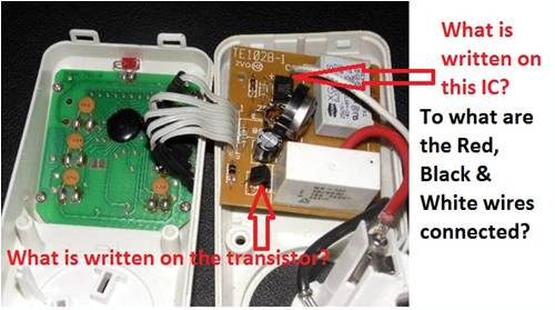
|
||||
Lapsy Senior Member Joined: 28/01/2012 Location: AustraliaPosts: 103 |
Only just noticed the post and feeling photographic Today, so here's more info pics... Regarding the wires that lead back to the socket pins, if you cant see the markings... Red - O/P Black - I/P White - COM Transistor number is - C945 P 76C If you need any more info, yell. Relay specs have been posted in a photo early on page 3 of this thread. I could run a search but would not really know what to search for. There is no "Brand" on the relay, just the specs in the pic on page. For quick ref they are... MR - 101 50/60Hz 16A 240V 24V Refer to pic on page 3 of this thread for full markings. All other sides of the relay are blank. Arlec have some website stuff that is probably useless to us here --> Click here!  This is my signature ---> Scribble, scrawl, a bit of light pencil shading, some indelable ink and a bit of caligraphy. |
||||
| larny Guru Joined: 31/10/2011 Location: AustraliaPosts: 346 |
Some extra photos as indicated would be useful please. Len |
||||
Lapsy Senior Member Joined: 28/01/2012 Location: AustraliaPosts: 103 |
The wire belt connecting the 2 boards together is to be cut later, for box/housing modding. It has had a solder repair already on the belt at the timer circuit end, so I prefer to not to touch that area again and would rather just slice through the middle, re-strip and extend the wires.  Speak soon... Speak soon...This is my signature ---> Scribble, scrawl, a bit of light pencil shading, some indelable ink and a bit of caligraphy. |
||||
| larny Guru Joined: 31/10/2011 Location: AustraliaPosts: 346 |
The "wire belt" is called a "ribbon cable" But don't cut it yet. I'm still trying to work out how the circuit works. Would you please set your meter to the continuity and diode setting, as shown in the photo of my meter. Then and connect the meter probes across the mystery component and record the reading then reverse the probes and record the reading again. Tell me what the readings are. I also need to know what the resistor values are. So I have attached the Altronics resistor info sheet from their website for you, so you know how to read the resistor colour codes. But it is not a good image as this forum does not allow you to upload .PDF docs. So I suggest that you download it from the data section of the Altronics website. You could also set your meter to the Ohms range and measure their resistances and therefore cross check your reading of the colour codes. However, note that you may not always read the correct resistance value with the meter because it may be shunted by another component on the PCB. 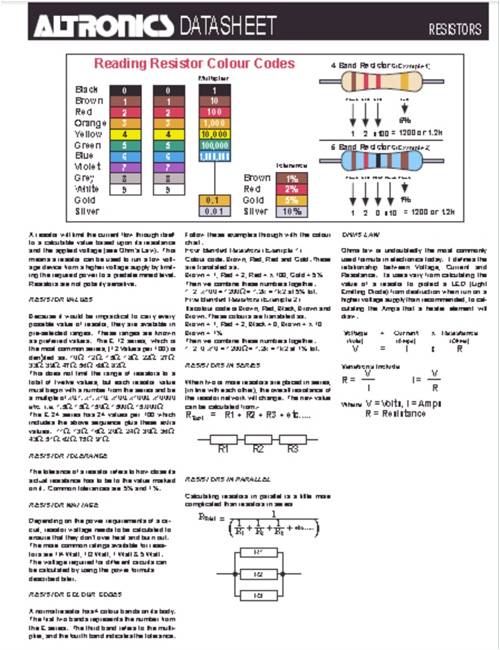
|
||||
Lapsy Senior Member Joined: 28/01/2012 Location: AustraliaPosts: 103 |
I will throw the results of the Multimeter up over the weekend. Speak soon...  This is my signature ---> Scribble, scrawl, a bit of light pencil shading, some indelable ink and a bit of caligraphy. |
||||
| larny Guru Joined: 31/10/2011 Location: AustraliaPosts: 346 |
While you're on the job, please have a look at the "Black Blob" IC in the photo to see if there is a number on it. I would like to know what it is. Len |
||||
| larny Guru Joined: 31/10/2011 Location: AustraliaPosts: 346 |
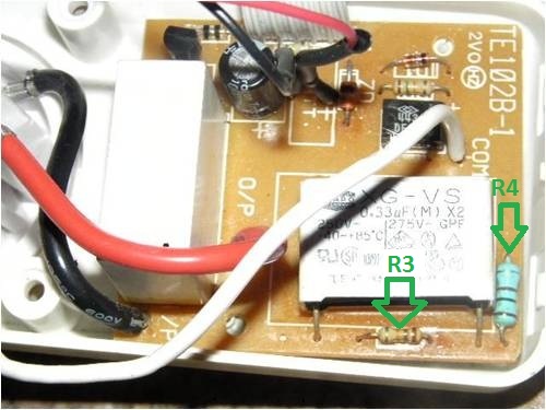
The photos below indicate what I want you to measure. Follow the instructions in my post dated 18 April. I have labelled the "mystery component" D1 as I think it is a diode. I have labelled the resistors R1 ~ R4 for your convenience. Len 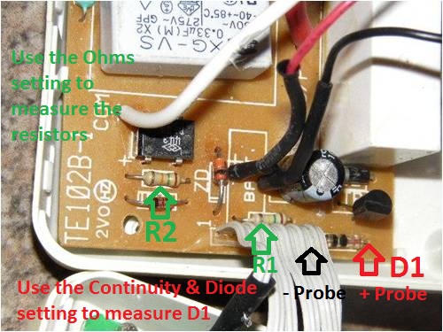
|
||||
Lapsy Senior Member Joined: 28/01/2012 Location: AustraliaPosts: 103 |
Ok, Seems do-able. Regarding the black blobbyness, no serial or any numbers to identify it. It is part of the timer board, I presume it is some sort of timing chip, maybe a 555 timer chip type thing possibly. That board connects to the programming (buttons) section (you probably figured that out already). Did unscrew that once for a look when repairing the ribbon cable (it broke away from its solder joint on the PCB) and the LCD display I noticed is not soldered on at all. LCD screen part contacts just through pressure from PCB being screwed down into position. It actually slid off into my hand and I had to pay attention as to which way it re assembled, but no major issue there. Let you know also, the picture of the multimeter you have shown is the same as mine. Following results are in 2 sets. With AA battery in... & WITHOUT AA battery. I figure I may as well attempt both results in case it indicates something to you. Battery needs to be in to switch the relay to on position, without it it does not seem to say on for very long. AA Battery in results Continuity/diode test D1 = 190 Continuity/diode test set on 20 setting R1 = Cannot seem to get a reading R2 = Cannot seem to get a reading R3 = AA Battery out results (NOTE: Relay only stays actively on on for abut 5 seconds before switching off) Continuity/diode test D1 = Fluctuates seemingly from around 340 up to about 505 Continuity/diode test set on 20 setting R1 = Cannot seem to get a reading R2 = Cannot seem to get a reading HOWEVER... Touching this resistor seemed to trigger the relay wildly. Slight contact here & there made it click away (if it is the relay switch clicking, note red LED indicator for power on flashes alongside this) R3 = Now.... bit of an issue. Timer now shorted out. Not working. Something happened, multimeter caught a surge & wigged out. Had to turn off then back on, multimeter re working again as usual. Timer now will not kick over as it used to. Somethings happened. Pretty certain it just fried itself. Timer is working on LCD display, buttons work. Did not seem to short it, pretty certain I only touched the resistor and was pretty careful not to bridge components with the multimeter probes. When attempting to activate it to the on position, it no longer passes current, so no longer working. The AA still runs the clock so looks like the one PCB is still working fine. The relay end is now buggerd I presume. I think it is safe to say I have f*#%ed it to be honest! Dammit & S*#t happens I suppose. Not to worry really, it was a recycle attempt. Was no normal use for it in the condition shown really. Not looking like something to hang off the mains from the pictures shown Where to from here? Can we use the timer display PCB and wire it into a new relay PCB setup specifically for 12v? If so, cost will be a factor once again, so time to weigh up that I guess. Secondly is it worth attempting to repair this? Maybe this section is not important for what I am after. Plan B please!  I threw in a round of applause for myself for the effort I threw in a round of applause for myself for the effort  Haha. Ah well... Haha. Ah well...
This is my signature ---> Scribble, scrawl, a bit of light pencil shading, some indelable ink and a bit of caligraphy. |
||||
Lapsy Senior Member Joined: 28/01/2012 Location: AustraliaPosts: 103 |

Just had a Plan B brainwave actually... so may as well post it while I'm in the moment. Thinking of a way out, what about using a water level sensor kit to trigger the pump? Same idea as the float, except the water level sensor lights up an LED to show the level remaining in the rainwater tank. Could we not tap into the power passing through the water level sensor? So when the water rises to a point where the LED indicator is lit up to show the level (E.G Full), it then triggers the pump to move the water from its container? Your 30 second circuit would still work in this case (to keep the pump going), OR just have the start & stop points regulated by sensor placement in the header tank? Just a thought, as I have 2 water sensor kits that run on 9v. I am going to fit one in a relatives rainwater tank. It is already assembled and works great. The second kit is unopened, so I wonder if I could possibly modify that to do the job? Somehow change a few components maybe to run the lot of 12v seems do-able. Might only need to change a few resistors in this case for 12v operation. If interested I can scan or take pictures of the kit and PCB for a look? Let me know your thoughts on this one? If it can be done, I will start another thread and record progress. I already have the spares and components, I might be halfway there already, and probably not as much troubleshooting as we have been doing here with the Arlec, as we are on DC power from scratch. This is my signature ---> Scribble, scrawl, a bit of light pencil shading, some indelable ink and a bit of caligraphy. |
||||
| larny Guru Joined: 31/10/2011 Location: AustraliaPosts: 346 |
You were not supposed to make the measurements with the power on! It did not occur to me that you would. You measure resistors, diodes, etc. with the power off. You won't get the right reading anyway or possibly no reading if the power is on. However, if the Timer Display still works, then all may not be lost. If the fault is on the Main PCB (the one with the relay) then we should be able to deduce what it is & fix. So I suggest that you check the resistors & diode with the POWER OFF and the battery out. NOte that you need to set the meter to the correct resistance setting. For example, say you are measuring a 100k resistor, then you need to set the meter to the next higest range (200k from memory). But if you were measuring say a 15k, then you would set it to the 20k range for better accuracy. So the general rule is - start with the meter set to the highest range & switch it to a lower range for accuracy. Did you understand how to read the colour codes? If so, tell me what they are. Len |
||||
| larny Guru Joined: 31/10/2011 Location: AustraliaPosts: 346 |
I'm now at the Kyabram library. You said that your trouble started when you touched a resistor connection. The relay operated & released wildly. That sounds to me like a dry joint. Have a close look at the resistor soldering. You will need a good magnifying glass. Look for a small hairline crack in the solder. Also look at the PCB tracks - there may be a small crack in one. And don't use the unit with the AA battery removed. That could damage the Black Blob IC. However, you said the LCD display & the buttons still work. That is a good sign. Can you set the time? I assume you are running the unit from 240 Volt. If so, be very careful as there will be a high AC voltage on the components. Avoid touching any metal with your hand. It is also a good idea to only use one hand. My time is about to run out. They only allow 30 minutes. So I'll come back tomorrow. Len |
||||
Lapsy Senior Member Joined: 28/01/2012 Location: AustraliaPosts: 103 |
All good mate! If you are away, enjoy that time. No panic here, not stressing over it. I can still measure the resistors, power off. Did private message you about power on measuring, but nothing was mentioned so went ahead anyways. In the diagram you provided, R3 caused the issue. R2 was no worries, just seemed to trigger the relay when touching. But I could have been sidestepping the power through it with the multimeter. One handed multimetering is my thing. I replaced one probe with an aligator clip a while back. Got sick of needing 3 hands haha! LCD still going, I can see the time and the settings function in that section via the buttons. Funny you mention this, worst case scenario I already thought about a last resort digital clock that runs of 1 x AA! 
I told you I am not throwing this thing out! 
Yes 240v is deadly, I wont be licking any circuits on mains at any stage, (Nor DC, neither are my desired flavours). I still like the water level sensor idea as well alot. See you when I see you, no rush.. This is my signature ---> Scribble, scrawl, a bit of light pencil shading, some indelable ink and a bit of caligraphy. |
||||
| larny Guru Joined: 31/10/2011 Location: AustraliaPosts: 346 |
I must have missed that point in the PM. I assume you mean that touching R3 caused the relay to flick. How was it powered? I assume it had to be from the 240 Volt. I don't see how the water level sensor is going to help you. I can't see much difference between it & the float switch method. Am I missing something? Len |
||||
Lapsy Senior Member Joined: 28/01/2012 Location: AustraliaPosts: 103 |
The difference between the float and the sensor is the float only gives you 15mm of play on the switch. Requiring a wide reservoir as discussed earlier in the thread. The Water level sensor gives you as much play as you like, as it is activated on a wire. When the wire is in the water the LED lights up to indicate level. Once the water drops below this wire, leaving no contact with the water, the LED will not light. You could have a sensor on the base of the header tank for example, and when the water runs out and there is no water contact with the sensor it would shut off the pump. At the top of the header would be another sensor, which would trigger say a pump to start emptying the tank, once it has refilled. When the water runs out again the bottom sensor detects this as it is no longer in contact with water for current to pass through and stops the pump. This would give you the option to use any size reservoir. You could even use something like 200mm storm pipe vertically, as long as the pump could handle the height. Obviously this needs to be modified slightly, just how to go about that it the thing. E.G both sensors would have to be in water to activate the pump. But as the level drops the top sensor is not going to be in water, as the water drains. We need the pump to continue pumping until the bottom sensor looses contact (from the water running out). At this point the pump stops. The container then continues to fill again and the cycle would start again as soon as booth sensors contact water again. Timed release of water would only depend on how fast the tank refills. So if you want to water things twice a day, say once every 6 hrs or whatever, you would need the tank to fill slowly over a 6hr period. This is your timer. It would also probably be a good idea to add a light sensor to this kit so the circuit turns off at nightfall and back on at sunrise. This would save power also. Just a thought. I think this is possible somehow... and starting on DC power from the beginning is a plus. The sensor kits are dirt cheap also. This is my signature ---> Scribble, scrawl, a bit of light pencil shading, some indelable ink and a bit of caligraphy. |
||||
| larny Guru Joined: 31/10/2011 Location: AustraliaPosts: 346 |
See comments above. I thought you were intending to pump the water into the tank & use gravity feed to water the plants. It does not matter to me, I can design it either way. If I understand what you want, it is a 6 Hour timer that opens a valve to let water flow into the tank & stop once the upper water sensor (or Float Switch) detects the water. And you want to start the sequence at dawn. Is this correct? Len |
||||