|

|
Forum Index : Electronics : Started Buck converter project
| Author | Message | ||||
| Warpspeed Guru Joined: 09/08/2007 Location: AustraliaPosts: 4406 |
That would be based on max expected input voltage, switching frequency, and maximum expected input current, and how much ripple voltage you feel is reasonable. Cheers, †Tony. |
||||
| govertical Guru Joined: 11/12/2008 Location: United StatesPosts: 383 |
I have to do some reading about shunt resistors, I have only seen it in one article since I started this project. I have no experience with the technique. just because your a GURU or forum administer does not mean your always correct :) |
||||
| govertical Guru Joined: 11/12/2008 Location: United StatesPosts: 383 |
Hi, does a mosfet have a power limit or is it limited by the amount of amps? I found a post about using a mosfet as a voltage controlled resistor and one of the responses referred to a wattage limit. On the data sheet there is a value for Maximum Power Dissipation . I have only been considering the Continuous Drain Current as the limit. Should I be using the Maximum Power Dissipation value to determine the current limit of circuit? This may explain why my test circuit stopped working. Comments welcome. just because your a GURU or forum administer does not mean your always correct :) |
||||
| Warpspeed Guru Joined: 09/08/2007 Location: AustraliaPosts: 4406 |
Current and power are two very different things. Current limit is usually set by the bonding wires that connect the silicon chip to the output pins. These are surprisingly fine wire that will blow like a fuse if too much current is passed through the device. 
Power is heat generation, that can cook the chip to the point of melting it to destruction. Fitting a heat sink helps, but there is a limit even to that. Your best bet is to keep well within BOTH the current and power limits if you expect it to be reliable for a very long time. Cheers, †Tony. |
||||
| govertical Guru Joined: 11/12/2008 Location: United StatesPosts: 383 |
Hi, I removed the four IRF510 and checked each one and they all passed. During that time I found a intermittent contact at the ground post going to battery. At this time I believe this problem was the main reason for all the other problems. So the circuit status is not as hopeless as I previously thought. It is always the little things. The shame is on me. I was also able to trace the source of the voltage spikes in the control signal back to the 555 timer. I am replacing the 4 IRF510 with 2 IRF540. The reasoning is the PD value is 100 watts, using two 2 in parallel will have a max PD of 200 watts and they should be able to handle the 15 amp limit that I am trying for. just because your a GURU or forum administer does not mean your always correct :) |
||||
| Warpspeed Guru Joined: 09/08/2007 Location: AustraliaPosts: 4406 |
Only with a very large heatsink. Cheers, †Tony. |
||||
| govertical Guru Joined: 11/12/2008 Location: United StatesPosts: 383 |
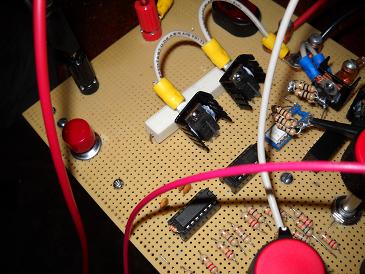
Hi, I have to find a better way to measure the voltage and current at the input, the circuit keeps destroying the cheap-o meters. These are the heat sinks on the IRF540ís. 
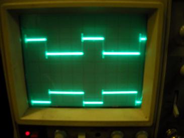
I was able to measure some values Vin = 33 volts Amps in unknown ( maybe 0.06) but I question the meters reliability, I believe the meter is damaged. Vout = 12.3 volts Amps out = 1.63 RPM = 180 control signal 20 kHz @ 40% duty cycle Highest circuit temperature = 82 degrees F 12 volt deep cell as load. control signals before the buck converter is turned on. 
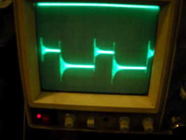
buck converter turned on: gate resistor signal 
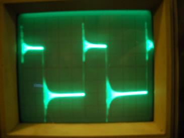
signal at Vs (mosfet source) 
So the circuit is working again. I will do more testing in the morning. I believe the ringing is from the 555 timers. Searching for solutions. Comments welcome just because your a GURU or forum administer does not mean your always correct :) |
||||
| govertical Guru Joined: 11/12/2008 Location: United StatesPosts: 383 |
Hi, replaced meter and measured 0.58 amps at input just because your a GURU or forum administer does not mean your always correct :) |
||||
| tonigau Newbie Joined: 15/10/2007 Location: AustraliaPosts: 4 |
Hi gov, [Quote] I believe the ringing is from the 555 timers. Searching for solutions. Comments welcome If you measure the ringing frequency you may be able to attribute it to some known circuit value such as MOSFET Drain-Source capacitance & switched inductance(including stray L) etc. Befor you dig too deep check first your measurment probe, often with high frequency measurement what the scope see's is not always what is present at the measurement point due to factors such as loop coupling. Loop coupling is via the unshielded portion of the probe (tip & ground wire). To test this, short the probe gnd wire to the probe tip & place the tip on your circuit points. If you see significant amplitude then you have coupling. To mitigate this effect you need to reduce the unshielded loop area or length. Do this by using the gnd ring of the probe (with the grabber removed) & the shortest possible ground connection. I have done this many time using a ring formed with a paperclip. T4 |
||||
| govertical Guru Joined: 11/12/2008 Location: United StatesPosts: 383 |
video of circuit operation New test data; rotor speed 500 RPM Vin 40voltsDC Iin 3amps Vout 12voltsDC Iout 6amps Duty cycle 50% Stators 4 coils per phase stator resistance < 1 ohm Circuit temp 82 degrees Fahrenheit Inductor temp 170 degrees Fahrenheit I need a better inductor. Replaced inductor with larger air core, had much better results. About 60 watts at input and about 60 watts at output. Analog meters used for measuring current. Larger inductor temp much cooler. It is nice to run a test without baking a meter. The measurement are better but not perfect. just because your a GURU or forum administer does not mean your always correct :) |
||||
| Warpspeed Guru Joined: 09/08/2007 Location: AustraliaPosts: 4406 |
It would help a lot if you can monitor the current with your oscilloscope, it will tell you a great deal. Cheers, †Tony. |
||||
| govertical Guru Joined: 11/12/2008 Location: United StatesPosts: 383 |
Hi, I configured the PMA using just 2 stators to form a 3 phase star, 8 coils per phase. Phase to phase resistance = 9 ohms. Rotor RPM________ Voc DC 100______________ 15 200______________ 30 300______________ 45 400______________ 60 500______________ 75 Rotor RPM_________Vin DC____Amps in________Amps out 100_______________16.5______?______________0.2 200_______________27.3______0.2____________1.0 300_______________28.8______2.0____________5.0__Vout=12.8Vdc Free wheeling diode temp = 82 degrees F 50% duty cycle test fixture limit 300 RPM using load Vout = 12 volt deep cell test load measurements ball park , 60 Watts appears to be the limit of test fixture under load. I have to remove one stator and rotor and then I will be able to road test. Search for ideas on how to limit voltage to 100 volts at the input to protect circuit. Comments welcome I am do not how to measure current with a O-scope. I am researching the method. just because your a GURU or forum administer does not mean your always correct :) |
||||
| govertical Guru Joined: 11/12/2008 Location: United StatesPosts: 383 |
Maximum current output without using the circuit is 2 amps. The circuit is definitely is a benefit. 
just because your a GURU or forum administer does not mean your always correct :) |
||||
| BlueSmoke Newbie Joined: 02/05/2013 Location: United StatesPosts: 25 |
Great thread, (glad I found it) this should help me understand more about Buck Converters. (I haven't digested the complete thread yet ... but will). I'm not sure if I should try to make one or perhaps look for a kit or pre-made unit but reading more here should help me figure that out. Thanks for the posts, BlueSmoke PS: Do you have any recommendations for a fairly low amp (perhaps 20A) MPPT controller circuit via ebay or other (pretty low budget here)? I'll do more research in this area, just looking for recommendations if they are out there. Thanks! |
||||