| |
  Page 5 of 7 Page 5 of 7   |
| Author |
Message |
adonis
Regular Member

Joined: 13/02/2010
Location: SwedenPosts: 42 |
| Posted: 06:16pm 19 Feb 2010 |
 Copy link to clipboard Copy link to clipboard |
 Print this post |
|
if you go from high to low voltages, at what voltage does the op3 output go low? |
| |
adonis
Regular Member

Joined: 13/02/2010
Location: SwedenPosts: 42 |
| Posted: 06:20pm 19 Feb 2010 |
 Copy link to clipboard Copy link to clipboard |
 Print this post |
|
im gonna put my kids to bed, will be back in 30min. |
| |
kalamidas
Newbie

Joined: 19/02/2010
Location: GreecePosts: 21 |
| Posted: 06:21pm 19 Feb 2010 |
 Copy link to clipboard Copy link to clipboard |
 Print this post |
|
14,4v op3 is 1,43 |
| |
adonis
Regular Member

Joined: 13/02/2010
Location: SwedenPosts: 42 |
| Posted: 06:44pm 19 Feb 2010 |
 Copy link to clipboard Copy link to clipboard |
 Print this post |
|
ok. thats not right. is your 10k and 100k resistors connected correctly? |
| |
Bub73

Senior Member

Joined: 10/12/2009
Location: United StatesPosts: 116 |
| Posted: 06:50pm 19 Feb 2010 |
 Copy link to clipboard Copy link to clipboard |
 Print this post |
|
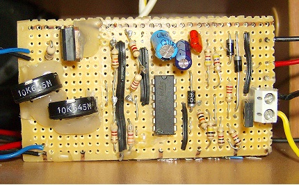
can you post a photo of your board ?
Also check the value and location of the 10k resistor and jumpers.
Bob |
| |
kalamidas
Newbie

Joined: 19/02/2010
Location: GreecePosts: 21 |
| Posted: 07:52pm 19 Feb 2010 |
 Copy link to clipboard Copy link to clipboard |
 Print this post |
|

this is the photo |
| |
Bub73

Senior Member

Joined: 10/12/2009
Location: United StatesPosts: 116 |
| Posted: 08:31pm 19 Feb 2010 |
 Copy link to clipboard Copy link to clipboard |
 Print this post |
|
I don't see one of the jumpers for paralleling the pots, are they both there ?
I'll look closer later.
Bob |
| |
kalamidas
Newbie

Joined: 19/02/2010
Location: GreecePosts: 21 |
| Posted: 08:35pm 19 Feb 2010 |
 Copy link to clipboard Copy link to clipboard |
 Print this post |
|
it is there under the silicon right side of the low volt trimmer |
| |
adonis
Regular Member

Joined: 13/02/2010
Location: SwedenPosts: 42 |
| Posted: 08:40pm 19 Feb 2010 |
 Copy link to clipboard Copy link to clipboard |
 Print this post |
|
sorry, my kids refuse to fall asleep. but here is perhaps a small explanation to help you troubleshoot. the problem seems to lie in the feedbackloop in OP3, the signals from OP1 and 2 seems to be ok, so the trimpots, R1 and R2 is probably working as they should.
the purpose of the 10k in series with the 100k is to keep OP3 high until a high signal from OP2 turns it low.
when the voltages is between 12 and 15 volt both OP1 and 2 are low, and the diod (4001) makes sure that OP3 stays low if it already is low.
if it is high, (as it is when the voltages drops from above 15V) the resistors in series keeps it high.
the potential between the two resistors should be Vop3out*(100/110) and this is also what OP3+in sees. this is not the case in your controller, so there might be a problem in this resistor pair, or in their surrounding connections.
hope this helps. |
| |
kalamidas
Newbie

Joined: 19/02/2010
Location: GreecePosts: 21 |
| Posted: 08:46pm 19 Feb 2010 |
 Copy link to clipboard Copy link to clipboard |
 Print this post |
|
thanks for your time ,i hope i didnt keep you away from your kids, after all they have priority.
i will check the resistors and the surroundings. |
| |
Bub73

Senior Member

Joined: 10/12/2009
Location: United StatesPosts: 116 |
| Posted: 09:25pm 19 Feb 2010 |
 Copy link to clipboard Copy link to clipboard |
 Print this post |
|
Yes adonis is right on op3; check the values of the resistors with your ohms meter a mismarked resisitor could cause no end of trouble here and on the bd139 as well.
Bob |
| |
adonis
Regular Member

Joined: 13/02/2010
Location: SwedenPosts: 42 |
| Posted: 09:54pm 19 Feb 2010 |
 Copy link to clipboard Copy link to clipboard |
 Print this post |
|
no worries, i gave them priority. hope you get it together!
|
| |
Downwind

Guru

Joined: 09/09/2009
Location: AustraliaPosts: 2333 |
| Posted: 11:56pm 19 Feb 2010 |
 Copy link to clipboard Copy link to clipboard |
 Print this post |
|
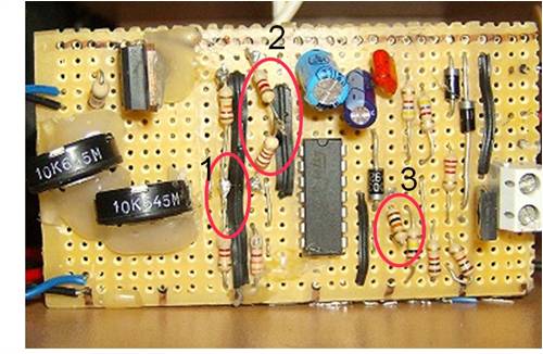
I have a few questions about the board as its a bit hard to see clearly.

1...looks incorrect to me(solder bridge??)
2...What is the combined resistance of R1 here.
3...What value is this resistor as it looks like 1K and should be 10K
...................................................
What voltages do you have on pins 5,6,7 as looks to be something wrong with op2 voltage, as when op1 (pin1) goes low the relay switches off.
This would indicate op2 (pin7) was high, at the time op1 goes low.
Op2 should be low (1.2 -1.5v) and go high when the voltage is around 12v or adjusted to suit.
You will need to check op2 voltage and get that to be high at 12 volts and go low at about 0.2 volts above 12v.
This not happening so no hysterisis.
Pete
Sometimes it just works |
| |
Bub73

Senior Member

Joined: 10/12/2009
Location: United StatesPosts: 116 |
| Posted: 01:04am 20 Feb 2010 |
 Copy link to clipboard Copy link to clipboard |
 Print this post |
|
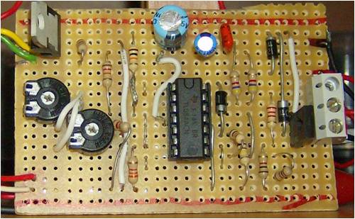
I also noticed you did not use a socket for the ic, so I must ask what type of iron and heat settings you used when soldering on the chip itself especially if you have tried more than one.
Bob |
| |
kalamidas
Newbie

Joined: 19/02/2010
Location: GreecePosts: 21 |
| Posted: 07:18pm 20 Feb 2010 |
 Copy link to clipboard Copy link to clipboard |
 Print this post |
|
hello again and thamks for your questions shows that you game me some time.
answers
Bob i used standard solder and a 60 watt solderind device(i dont know the english word for it).
in this bord i did not tried other ic's.
i tried them on the second board atemting to debug the board
Pete
1 i just cut the resistor and test the resistanse and then resolder it again it seems that is bridged but it is not i left some of the wire and it is above the other resistor show it seems like a bridge.
2.the combined resistance on my multimeter is 10,2k oms
an 8k and a 2,2k
3 10k the last one i had it has a thiker red line, 3 times check on my multimeter .
I will leave this bord for the time and i will try again with a new one.so i can cross check the two boards.for the hysterisis problem i will just power the controller from the windmill not the bateries.
what do you thing about that? |
| |
Bub73

Senior Member

Joined: 10/12/2009
Location: United StatesPosts: 116 |
| Posted: 08:06pm 20 Feb 2010 |
 Copy link to clipboard Copy link to clipboard |
 Print this post |
|
Use a socket this time for the ic they are cheap or even a used one if you have some junk around; this will keep the heat and possible static from your soldering iron off the chip itself and make it easy to swap out chips without damage.
Then install the chip tl084 last.
You also need some type of varible power supply to set the high and low pots; using the windmill alone may let the magic smoke out.
BobEdited by Bub73 2010-02-22 |
| |
Downwind

Guru

Joined: 09/09/2009
Location: AustraliaPosts: 2333 |
| Posted: 12:48am 21 Feb 2010 |
 Copy link to clipboard Copy link to clipboard |
 Print this post |
|
I dont think i would power the board from the windmill only, as the voltage may well exceed the chips rating.
Pete.
Sometimes it just works |
| |
adonis
Regular Member

Joined: 13/02/2010
Location: SwedenPosts: 42 |
| Posted: 06:46am 21 Feb 2010 |
 Copy link to clipboard Copy link to clipboard |
 Print this post |
|
i previously suggested to use smaller resistors before the led:s. this might be a bad idea since the tl084 is not built for very large output currents. could someone with more knowlige tell us if this would burn the chip?
/jonathan |
| |
kalamidas
Newbie

Joined: 19/02/2010
Location: GreecePosts: 21 |
| Posted: 08:50am 21 Feb 2010 |
 Copy link to clipboard Copy link to clipboard |
 Print this post |
|

this is the third board and this is the readouts
12v 13.5v 15v
0.61 1 14 6.46 0.61 1 14 6.46 0.61 1 14 6.45
3.53 2 13 3.92 3.71 2 13 3.94 3.89 2 13 3.34
2.83 3 12 5.90 3.21 3 12 5.90 3.47 2 12 5.90
7.89 4 11 0.01 7.89 4 11 0.01 7.89 4 11 0.01
2.85 5 10 0.01 3.21 5 10 0.01 3.47 5 10 0.01
2.86 6 9 7.10 3.21 6 9 7.32 3.47 6 9 7.32
7.10 7 8 590 7.28 7 8 5.90 7.32 7 8 5.90 |
| |
kalamidas
Newbie

Joined: 19/02/2010
Location: GreecePosts: 21 |
| Posted: 08:54am 21 Feb 2010 |
 Copy link to clipboard Copy link to clipboard |
 Print this post |
|
12v 13.5v 15v
0.61 =1 14= 6.46 0.61= 1 14 =6.46 0.61 =1 14= 6.45
3.53= 2 13= 3.92 3.71= 2 13= 3.94 3.89= 2 13 =3.34
2.83= 3 12 =5.90 3.21= 3 12= 5.90 3.47=3 12= 5.90
7.89 =4 11= 0.01 7.89= 4 11= 0.01 7.89 =4 11= 0.01
2.85= 5 10= 0.01 3.21 =5 10= 0.01 3.47 =5 10= 0.01
2.86= 6 9= 7.10 3.21 =6 9= 7.32 3.47= 6 9= 7.32
7.10 =7 8= 590 7.28 =7 8= 5.90 7.32= 7 8= 5.90 |
| |
| |
  Page 5 of 7 Page 5 of 7   |

