Home
JAQForum Ver 24.01
Log In or Join  
Active Topics
Local Time 04:39 06 Aug 2026 Privacy Policy
Jump to

Notice. New forum software under development. It's going to miss a few functions and look a bit ugly for a while, but I'm working on it full time now as the old forum was too unstable. Couple days, all good. If you notice any issues, please contact me.

Forum Index : Electronics : Wiseguy (WG) Inverter Build Discussions Australia

     Page 5 of 5    
Author Message
GleamBright
Regular Member

Joined: 21/04/2025
Location: Australia
Posts: 41
Posted: 01:13am 28 Jul 2026
Copy link to clipboard 
Print this post

A couple of questions about Nanos and the overcurrent Hall sensor, before committing to purchase:

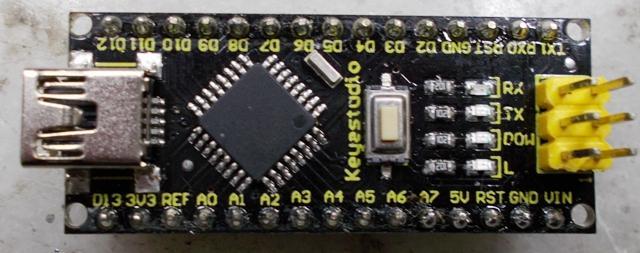
- are there any preferences for the type of Nano Chip. taking into account KeepIS' prior comments re: chip types to avoid, and uploaders? Am I better off paying extra for the Keye Studio type, go for the Chinese cheapie, or some other type?

- re: Hall sensor. KeepIS specified 12V 500A for his dual stage inverter. What Amp rating would suit a single stage system rated at 6 kW?


KeepIS

Guru

Joined: 13/10/2014
Location: Australia
Posts: 2212
Posted: 01:51am 28 Jul 2026
Copy link to clipboard 
Print this post

A single stage Inverter can handle 600A Peak DC input. A dual inverter has TWO 500A units, one for each power stage. Make sure it's a DC (uni directional) Sensor like the ones I posted.  

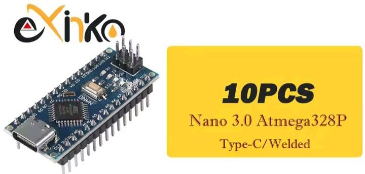
Most Nano boards are fine, I've been running some low coast units for a few years. Keep in mind that some come with the pins fitted, others supply the pins but you have to solder them in.

I've used these Nano V3  Core Electronics AU $6.55 EX GST.
.
Edited 2026-07-28 11:52 by KeepIS
NANO:Inverter V 8.4ksLinux AvrDude GUI script V4.1
 
KeepIS

Guru

Joined: 13/10/2014
Location: Australia
Posts: 2212
Posted: 08:35am 04 Aug 2026
Copy link to clipboard 
Print this post

I just finished building one of the new WG power boards, this is the one with two very small vertical mounted gate drive PCBs. The power board is slightly shorter than the old board, and it allows the FET ferrite beads to be fitted without any gymnastics on the High side drains, really nice!

This new power board is the simplest and quickest board to build of all, however the SMD gate drives PCB's are time consuming, but they are easy to build with plenty of room between components. As usual, the trickiest parts are the resistors and caps, but that's coming from someone who dislikes soldering tiny SMD components anyway, and it took me longer as I was checking every component before and after it was soldered in.

This is my first build of the new board with its revised construction and layout, so I also noted the things that might trip up new builders, there will soon be some people building this inverter, likely some with little or no experience, I now feel confident that this is indeed the best version for them to build.

It's definitely the best version of all from a construction point of view, especially the revised FET layout and Isolated supply mounting, it's pretty close to fool proof now.

Anyway, before calling it a day, I fitted four FETs, the test Toroid and chokes, NO caps, powered it, it worked first go 

I'll make another tomorrow, should be a lot faster this time.
.
Edited 2026-08-05 08:43 by KeepIS
NANO:Inverter V 8.4ksLinux AvrDude GUI script V4.1
 
     Page 5 of 5    
Print this page


To reply to this topic, you need to log in.

The Back Shed's forum code is written, and hosted, in Australia.
© JAQ Software 2026