
|

|
Forum Index : Microcontroller and PC projects : Game*Mite: handheld game console based on PicoMite
| Author | Message | ||||
| thwill Guru Joined: 16/09/2019 Location: United KingdomPosts: 4037 |
I'm at a loss then as that's the same for me (though our perceptions of "quiet" and "sufficiently loud" may be different). PLAY SOUND and PLAY MODFILE go through the same PWM, pins, filter, amplifier and speaker so I don't know why one is OK and the other is not. You could try nuking the Pico and installing the GameMite-1.1.0-full.uf2 flash image; as you said when you enabled the MODBUFF it didn't clear A:/ and I think it should have done, so maybe something odd going on there ??? It shouldn't be relevant here, but a design note about the audio. It uses a PAM8302 mono differential amplifier, and the original intent was to use PLAY SOUND's MONO flag whereby GP19+GP20 would carry a mono signal and its inverse to A+ and A-. However after the first PCB (1.0.0) was laid out: 1. I realised that such a configuration would only work with PLAY SOUND, not PLAY MODFILE, PLAY WAV, etc. 2. Whilst playing on a breadboard I accidentally wired it up incorrectly and discovered you would get sufficient volume with A- tied to ground. As a result the Game*Mite now mixes the standard PWM stereo signal through resistors and sends that to A+. We could have switched to a proper stereo PAM8403 but that module has a larger footprint and TBH you really don't need stereo sound for a device such as this - YMMV. Best wishes, Tom Edited 2023-10-04 02:00 by thwill Game*Mite, CMM2 Welcome Tape, Creaky old text adventures |
||||
| Martin H. Guru Joined: 04/06/2022 Location: GermanyPosts: 1113 |
The new display just arrived and Gui Calibrate worked straight away. So it was the display. Thanks for your help with troubleshooting. Cheers Martin 'no comment |
||||
bigmik Guru Joined: 20/06/2011 Location: AustraliaPosts: 2914 |
Hi Martin, All, That is great news. Boiling it down, The one without the chip (also won’t have the touch panel fitted) obviously wont work for touch. The other had a cracked glass, which would be the touch glass, depending on where the crack is certain areas may work and others not, but calibrate relies on about 90% of the touch area to be good. I have a 4” ILI9488 that has a crack on one corner so that area is dead but the rest is functional. Good luck with playing with your GameMite. Regards, Mick Edited 2023-10-06 08:32 by bigmik Mick's uMite Stuff can be found >>> HERE (Kindly hosted by Dontronics) <<< |
||||
| thwill Guru Joined: 16/09/2019 Location: United KingdomPosts: 4037 |
Hey folks, @Mixtel90 has had some "fun" with one of the latest batch of 1.3.1 PCBs  . .Between batches we replaced the original 1.3.1 Gerbers which used untented vias with a version that had tented vias (i.e. ticked a check-box) ... and then a bug in the PCB software @bigmik was using decided it would be more interesting to scatter part of the board with a handful of random ground segments  . .- None of the delivered boards (with the exception of @Mixtel90's) have this problem. - @karlelch your board (in the post) does have this problem, as soon as I have new ones from China I will put a replacement PCB in the post to you. I have also sent you a PM and eBay message but you haven't responded hence posting here too. - I have temporarily removed the Gerbers from GitHub until I've received and built a 1.3.2. - Many apologies if anyone had a set of the faulty 1.3.1 PCBs privately fabricated. - Lesson learnt  . .Best wishes, Tom Edited 2023-10-10 18:48 by thwill Game*Mite, CMM2 Welcome Tape, Creaky old text adventures |
||||
| Mixtel90 Guru Joined: 05/10/2019 Location: United KingdomPosts: 6786 |
Oh, fun indeed! :) Assembly went well - the instructions are good - but the debugging was "interesting" - and some of it was my own fault. :( Lets get the nasty bit over first. I've highlighted three positions where there were shorts to GND on the PCB. Initially I thought there was a bubble in the etching, but it turned out to be the gerbers that had the problem (after viewing them in SL6). 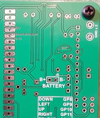 The top one was easy to spot, the two pad ones not easy to find at all because they looked deliberate. Note that the board in the photo is not the actual board but an earlier version which doesn't have the problem. Right - the kit. I was pleased to see good packaging and antistatic bags used. Resistors had their values marked on them, which is great for those of us with less than perfect eyes or those for whom 4-band resistors are still confusing. :) At the bottom left you can see my "secret weapon", of which more shortly. 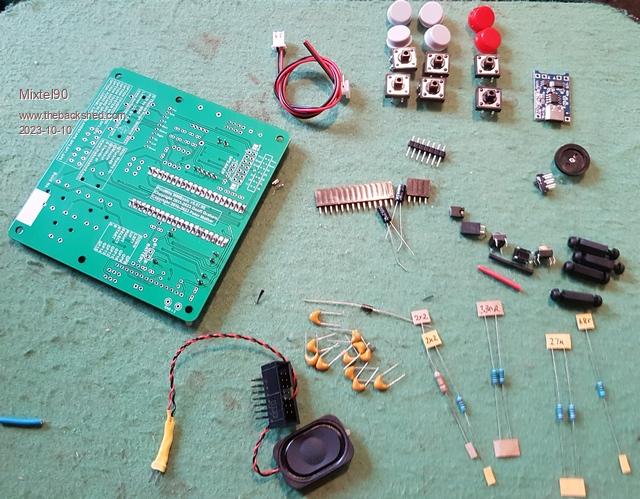 When trimming the male header pins be careful. They are hard (I suspect they may be plated and tinned steel rather than copper as they seem to be slightly magnetic). Don't use your best flush-cutters as you'll soon blunt them. You do need a flush cut though, so I'd recommend using old cutters or buying some cheap ones for the job. The bits fly off in all directions - you *need* eye protection. This is where my secret weapon comes in: 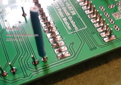 Put it onto the pin then snip below it. Pull the snipped bit out. 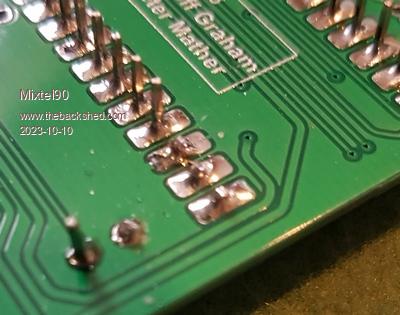 It's done. Nothing flies away (well, not often) and your fingers don't get bits of pin stuck in them. And finally it's done. The battery is actually two free, reclaimed disposable vape batteries wired in parallel. (Link them in parallel but via a 10R or 12R resistor for a few hours to equalize their voltage before actually making the final connection). I replaced the spacers with 15mm ones to allow for the battery diameter. The 68R resistor is tacked onto the bottom - I had to pull it out during debugging and gave up on trying to put it back! 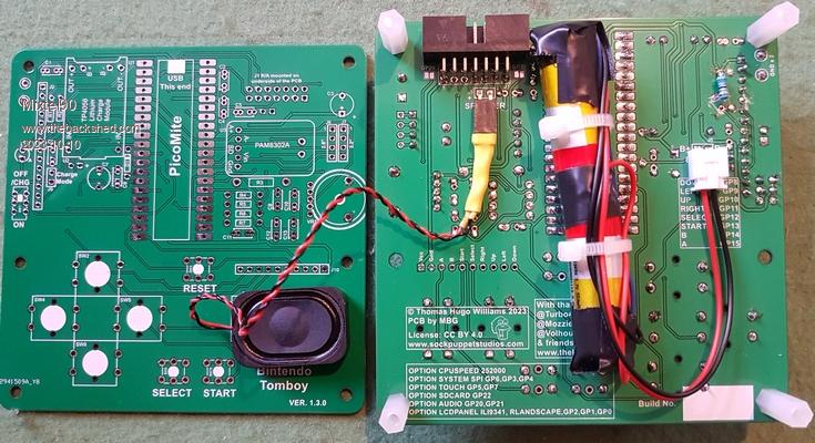 Loading the software was slightly confusing as, firstly, Tom's file name doesn't seem to agree with the one on Github and, secondly, I'm not that familiar with Github anyway so it was a bit of an adventure. Once I'd got it there was no problem in installing it. The bits I got wrong? Partially soldered joint on OUT+ of the charger module prevented running on battery. There was another dry joint too. Edited 2023-10-10 20:18 by Mixtel90 Mick Zilog Inside! nascom.info for Nascom & Gemini Preliminary MMBasic docs & my PCB designs |
||||
| thwill Guru Joined: 16/09/2019 Location: United KingdomPosts: 4037 |
Hi Mick, I'm really glad you got there in the end, and sorry about the duff PCB, hopefully that is ironed out for the future. How so, do you mean that the manual refers to GameMite-<version>-full.zip and the files on GitHub actually include the version number, or something else ? Best wishes, Tom Edited 2023-10-10 20:38 by thwill Game*Mite, CMM2 Welcome Tape, Creaky old text adventures |
||||
| Mixtel90 Guru Joined: 05/10/2019 Location: United KingdomPosts: 6786 |
Yep. that was it. It just didn't dawn on me that it was the same thing at first. :) As I said, I'm mot a Github user and I don't have a grasp of how things are done on there. Incidentally, when soldering the modules onto the pins heat the pin and apply a bit of solder to it first, before heating the pad. Those pins conduct a lot of heat away from the joint. It's easy if you do it that way and you'll put less stress on the PCB pad. Edited 2023-10-10 20:44 by Mixtel90 Mick Zilog Inside! nascom.info for Nascom & Gemini Preliminary MMBasic docs & my PCB designs |
||||
bigmik Guru Joined: 20/06/2011 Location: AustraliaPosts: 2914 |
Hi Mixtel, All, The problem was caused by an obscure bug in DEX, With the 1.3.1 version I decided to try the option for curved traces instead of the usual orthogonal (45 and 90 degree bends) this was fine unfortunately I forgot to select TENTED VIAS, this means the vias were not covered by solder mask. In the scheme of things it meant nothing and in fact only one via was visible once the PCB is built. I decided to create Gerbers with the tented vias to pacify my (and Tom’s) OCD and our strive for perfection. It seemed an easy task as all I did was check the box for tenting and recreate the Gerbers. I always check them on one of the online Gerber viewers and I couldn’t see anything wrong and indeed I didn’t expect there to be anything different apart from the tenting so I didn’t check as thoroughly as I normally do. Unfortunately something went awry, the design looked perfect on screen but the Gerbers that DEX created were flawed. It was almost impossible to detect. In any case I have changed back to orthogonal traces and refilled the copper pours and recreated the Gerbers with tented vias. To not be trapped again with the faulty boards I have bumped the version number to 1.3.2, there is no electrical or physical difference to the non tented 1.3.1 boards. BTW no one who has purchased from me has the faulty 1.3.1 boards. Sorry for the hassle I put you through Mick but I know you like a challenge.   Kind regards Mick Mick's uMite Stuff can be found >>> HERE (Kindly hosted by Dontronics) <<< |
||||
| matherp Guru Joined: 11/12/2012 Location: United KingdomPosts: 9115 |
Mick Did a design rule check not pick it up? If not, this is a really bad bug which would undermine my confidence in ever again using a specific layout package |
||||
| Mixtel90 Guru Joined: 05/10/2019 Location: United KingdomPosts: 6786 |
Actually, I enjoyed the experience immensely. :) Knowing that others have these working was a huge advantage. I'm the bloke who had a water leak spraying into the kitchen from lead pipe on the live side of the stop tap on a saturday morning at the beginning of the summer holidays and couldn't find a plumber who would even consider coming out until after monday. I'm the one who did the National Lottery every week for about three years and never had a single tiny win on it. If this had worked first time it would have been a miracle. :) Mick Zilog Inside! nascom.info for Nascom & Gemini Preliminary MMBasic docs & my PCB designs |
||||
| karlelch Senior Member Joined: 30/10/2014 Location: GermanyPosts: 172 |
Thanks for letting me know and taking care of it. I just say your private message and responded you there as well. Best Thomas |
||||
| Mixtel90 Guru Joined: 05/10/2019 Location: United KingdomPosts: 6786 |
It's worth waiting for, Thomas. :) The faulty boards *can* be used, but they don't look too pretty after scraping out the larger of the three shorts. It's rather messy and not very nice on a new build. Mick Zilog Inside! nascom.info for Nascom & Gemini Preliminary MMBasic docs & my PCB designs |
||||
| karlelch Senior Member Joined: 30/10/2014 Location: GermanyPosts: 172 |
 |
||||
bigmik Guru Joined: 20/06/2011 Location: AustraliaPosts: 2914 |
Hi Peter, All, Did a design rule check not pick it up? If not, this is a really bad bug which would undermine my confidence in ever again using a specific layout package No, the design was correct, it was the Gerber generation that was incorrect. And of course I always do design rule checks before I fill copper pours and after as well. When I can get the time I will try to emulate the issue with a smaller board and then submit it as a bug. Dex is updated almost daily so in the course of a design I could see a dozen updates. Sometimes a new feature causes an obscure bug, generally they are not mission critical but when it’s the gerbers it is. Regards, Mick Mick's uMite Stuff can be found >>> HERE (Kindly hosted by Dontronics) <<< |
||||
| thwill Guru Joined: 16/09/2019 Location: United KingdomPosts: 4037 |
Hi folks, Well hopefully the v1.3.1 PCB issue is resolved and I've posted out replacement PCBs as required ... sorry again ... mea culpa ... I should have built one after we changed the Gerbers, no matter how subtly. The new (tested) v1.3.2 Gerbers can be found here: https://github.com/thwill1000/mmbasic-gamemite/tree/main/hardware/pcb-1-3-2 @bigmik and I both have stocks if anyone is interested. Aside: the onboard pot. on the PAM module is very fragile (or maybe just iffy) I ended up having to cut one off (it's not required) and replace it with the yellow bodge wire between A+ and the 1uF capacitor: 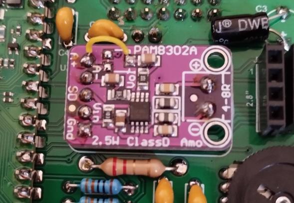 Best wishes, Tom Game*Mite, CMM2 Welcome Tape, Creaky old text adventures |
||||
| Mixtel90 Guru Joined: 05/10/2019 Location: United KingdomPosts: 6786 |
I'm enjoying being able to program on this system for some reason. :) It's advisable not to do what I did and overwrite flash slot 1 though. lol No, I'm not really sure what the program might be yet. It started off as a sort of graphic adventure thing and got diverted into a data packing exercise. Mick Zilog Inside! nascom.info for Nascom & Gemini Preliminary MMBasic docs & my PCB designs |
||||
| Volhout Guru Joined: 05/03/2018 Location: NetherlandsPosts: 4231 |
@Tom, There is a changelog on firmware only. What are the changes between 1.3.1 and 1.3.2 on the PCB ? Is it something I need to rework on mine ? Volhout PicomiteVGA PETSCII ROBOTS |
||||
| Mixtel90 Guru Joined: 05/10/2019 Location: United KingdomPosts: 6786 |
If your board has non-tented vias then there is no problem. If your board is 1.3.1 and has tented vias then it may have problems, but you would probably have noticed well before now! Boards from 1.3.2 onward (with tented vias) have the problem solved. I posted some photos of where to look for faults on a pcb earlier. Mick Zilog Inside! nascom.info for Nascom & Gemini Preliminary MMBasic docs & my PCB designs |
||||
| thwill Guru Joined: 16/09/2019 Location: United KingdomPosts: 4037 |
There is a changelog on firmware only. What are the changes between 1.3.1 and 1.3.2 on the PCB ? Is it something I need to rework on mine ? Volhout Hi Volhout, The changes between 1.3.0 and 1.3.2 were all supposed to be cosmetic only. Versions are: 1.3.0 tented vias - working final "Bintendo Tomboy" prototype 1.3.1 untented vias - working "Game*Mite" release, updated silk-screen 1.3.1 tented vias - broken Gerber with unwanted GND connections 1.3.2 tented vias - working again, actually 2 versions of the Gerbers, both tested: - gamemite-gerbers-1-3-2.zip - gamemite-gerbers-jlcpcb-1-3-2.zip - has additional silkscreen text JLCJLCJLC so that JLCPCB will put the batch number in a specific place (checkbox when ordering) Even though there are some things I would do differently if starting from scratch (e.g. use a shift-register for the controller to free up more I/O for hacking) it's not my intention that there will be future incompatible changes to the Game*Mite circuit. Thanks to @bigmik the Game*Mite PCB meets or exceeds all my design goals including the "build-it-yourself" and "hackability" ones. What I need to do now is work on extensions to the software plus Peter's new firmware enhancements make it much more capable than originally anticipated and also mean that going forward I shouldn't need to maintain a distinct version of MMBasic. Best wishes, Tom Edited 2023-10-20 22:52 by thwill Game*Mite, CMM2 Welcome Tape, Creaky old text adventures |
||||
| PhilP Newbie Joined: 25/01/2017 Location: United KingdomPosts: 31 |
Hi Tom et al - I built my Game*Mite last week with a 1.3.1 board. It seems to work OK except I am rubbish at the games. Loading the software from the link in the manual was easy. The only strange thing I noticed is that the blue charge light never goes out when the battery should be charged. I have tried with the jumper in both positions. The construction wasn't too bad except some of the spacing of the module connections required a bit of bending of leads. I started following the instructions as it all looked complicated but once I could see the bigger picture I just did it my way. I did not see that the use of the second board to line up pins was necessary. It was good to put together an already assembled kit of parts. I expect I will use the Game*Mite as portable battery driven unit for other uses e.g. GPS tracker. Thanks team Game*Mite Phil |
||||