|

|
Forum Index : Microcontroller and PC projects : Getting the best out of Pico ADC
| Author | Message | ||||
| NPHighview Senior Member Joined: 02/09/2020 Location: United StatesPosts: 200 |
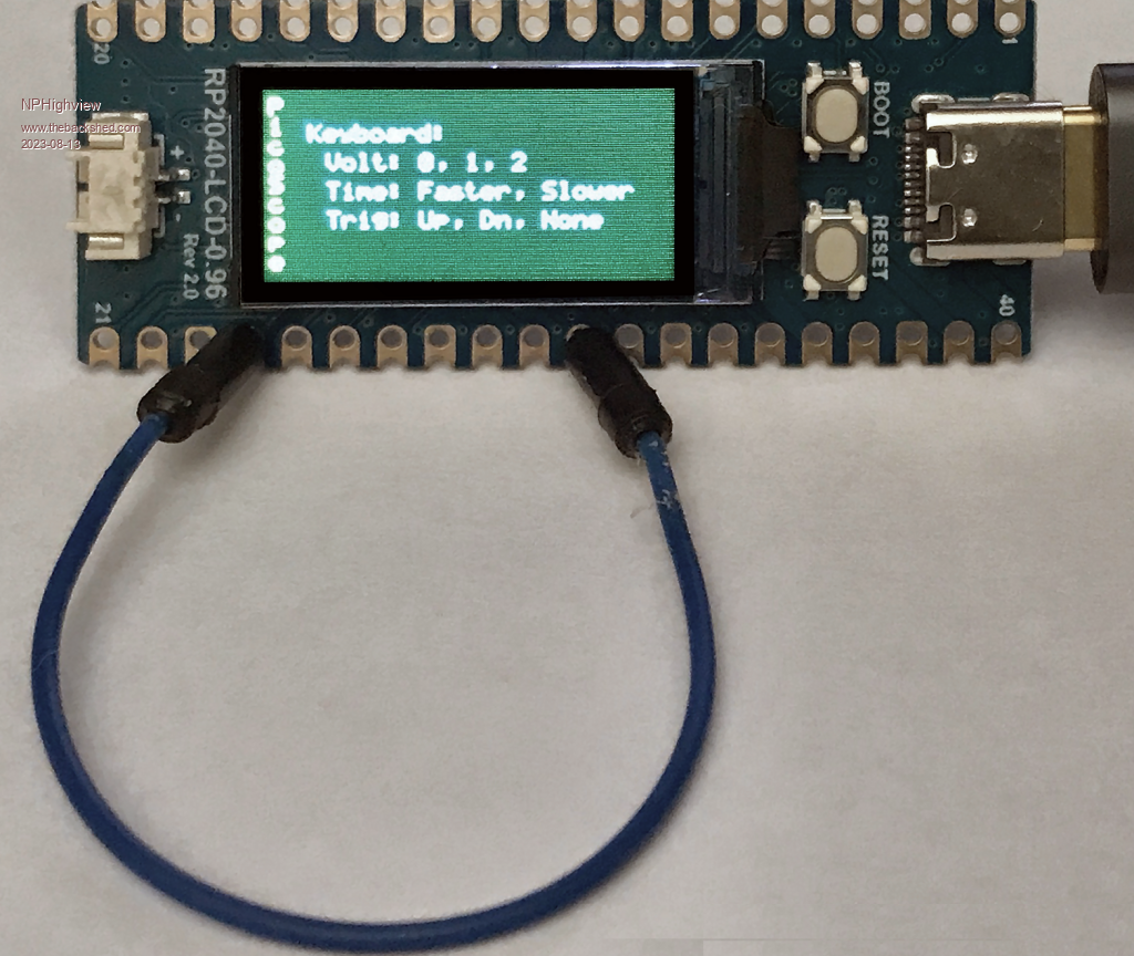
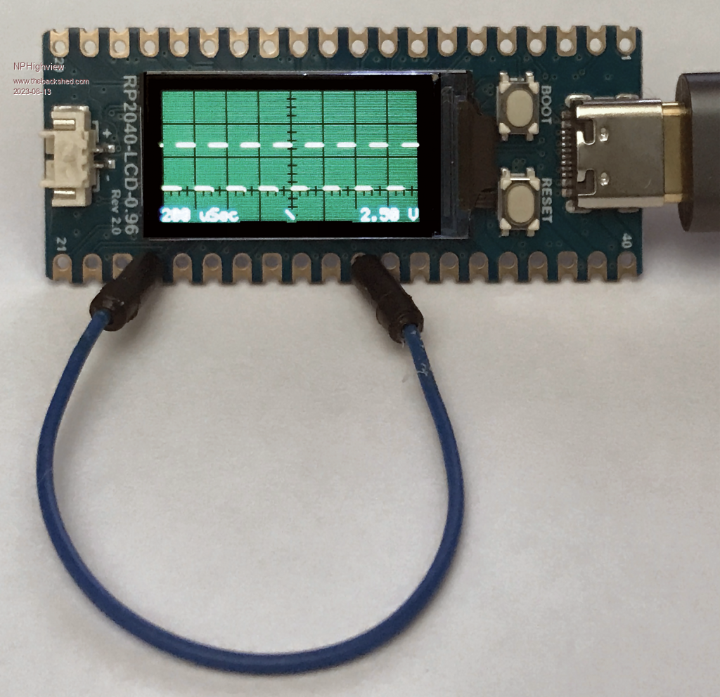
OK - now we're getting somewhere. The listing below is for a fairly general purpose single-channel oscilloscope on the Waveshare RP2040-LCD-0.96. Three voltage ranges, six timing ranges, and three triggering modes are selectable via either terminal emulator or debounced front-panel switches. The code displays a "lost trigger" message if none has been detected in 2.5 seconds, and recovers when the trigger is restored or the trigger condition is changed. Now, on to design for a carrier board with probe lead jacks, and a 3D printed enclosure!   ' PicoScope - a simple oscilloscope on the RP2040-LCD-0.96 ' NPHighview (Steve Johnson) August, 2023 ' ' Test Signal output on GP18 / Pin 24 ' Analog Signal input on GP26 / Pin 31 ' ' Scope Controls (via serial input from terminal emulator): ' Voltage: 0, 1, 2 to change vertical scale ' Time: Faster, Slower to change horizontal scale ' Trigger: Up, Down, None to change trigger criteria ' ' Sampling, Test Signal, Triggering, Framebuffers from stanleyella ' Math & Memory Copy from matherp ' Ganssle's switch debounce routine from CaptainBoing and NPHighview ' Graticules, Array Drawing, variable scales & triggering from NPHighview Option EXPLICIT Const PWM_Freq = 5000 ' Frequency for Test Signal on Pin 24 Const Debounce = &H7FF ' Debounce delay for front panel switches Const Hres = MM.HRes ' Horizontal screen resolution Const Vres = MM.VRes ' Vertical screen resolution ' Specifically For Waveshare RP2040-LCD-0.96 Const Major = Vres/4 ' Major tic mark spacing Const Minor = Major/4 ' Minor tic mark spacing Const V_sw = 1 ' GP0 on the Pico and Waveshare RP2040-LCD-0.96 Const T_sw = 2 ' GP1 "" Const A_sw = 4 ' GP2 "" ' Generic to all displays Const HMajor = Hres/Major ' How many Horiz Major Tic marks Const VMajor = Vres/Major ' How many Vert Major Tic marks Const HMinor = Hres/Minor ' How many Horiz Minor Tic marks Const VMinor = Vres/Minor ' How many Vert Minor Tic marks Const Background = RGB(32,64,32) ' Color for Display background, a la Tektronix scopes Const GMajor = RGB(black) ' Color for Major tic marks Const GMinor = RGB(black) ' Color for Minor tic marks Const Signal = RGB(yellow) ' Color for displayed signal Const TxtColor = RGB(cyan) ' Color for displayed text Const Trig_None = 0 Const Trig_Down = 1 ' Enumerate possible trigger conditions Const Trig_Up = 2 Const ADC_Max = 5 Const V_Max = 2 Const Trig_Max = 2 ' Declare storage Dim INTEGER c, n, x, y, trigger, Vselect, Trig_Type, ADC_select Dim INTEGER v_btn, t_btn, a_btn ' Counters to do switch debouncing Dim INTEGER Horizontal(Hres) ' Horizontal coordinate buffer for fast graticule and buffer draw Dim FLOAT sample(2*Hres) ' Extra size to hopefully pick up a trigger event Dim FLOAT buffer(Hres) ' Display buffer for screen output Dim INTEGER addr.sample, addr.buffer Dim INTEGER HMajorX1(HMajor+1), HMajory1(HMajor+1), HMajory2(HMajor+1) ' For Horizontal Major Axes Dim INTEGER VMajorX1(VMajor+1), VMajorx2(VMajor+1), VMajory1(VMajor+1) ' For Vertical Major Axes Dim INTEGER HMinorX1(HMinor+1), HMinory1(HMinor+1), HMinory2(HMinor+1) ' For Horizontal Minor Axes Dim INTEGER VMinorX1(VMinor+1), VMinorx2(VMinor+1), VMinory1(VMinor+1) ' For Vertical Minor Axes Dim Float V.Scale(10), V.Offset(10), V.MajVolts(10) Dim Float H.Freq(10), H.Seconds(10) Dim String H.Units$(10), keypress$ ' ========================== Initialization ================================= Initialize_Arrays Initialize_Hardware Display_Instructions Draw_Graticules ' ========================== Processing Loop ================================ Do Randomize_Test_Signal Timer = 0 Do Handle_Keypresses Handle_Switches trigger = -1 Get_Samples trigger = find_trigger(Trig_Type) If Timer > 2500 Then Display_No_Trigger ' Waiting too long for a trigger. Loop Until trigger >= 0 If Timer > 2500 Then Draw_Graticules ' OK, we've got a trigger. Clear message. Scale_Samples Update_Display Loop ' ========================== Subs and Functions ============================ Sub Handle_Keypresses keypress$ = Inkey$ Select Case keypress$ Case "0" : Vselect = 0 Case "1" : Vselect = 1 Case "2" : Vselect = 2 Case "u", "U" : Trig_Type = Trig_Up Case "d", "D" : Trig_Type = Trig_Down Case "n", "N" : Trig_Type = Trig_None Case "f", "F" : ADC_select = Min(ADC_select+1, 5) : Set_ADC_Timing Case "s", "S" : ADC_select = Max(ADC_select-1, 0) : Set_ADC_Timing Case "" : Exit Sub ' No key pressed. No change. Case Else : Display_Instructions ' Unknown key pressed. End Select Draw_Graticules End Sub Sub Handle_Switches ' using Ganssel's debounce routine in Fruit of the Shed Local INTEGER V, T, A v_btn = v_btn<<1 Xor Pin(V_sw) And Debounce t_btn = t_btn<<1 Xor Pin(T_sw) And Debounce a_btn = a_btn<<1 Xor Pin(A_sw) And Debounce If v_btn = 0 Then Vselect = (Vselect+1) Mod (V_Max+1) v_btn = Debounce EndIf If t_btn = 0 Then Select Case Trig_Type Case Trig_Up: Trig_Type = Trig_Down Case Trig_Down: Trig_Type = Trig_None Case Trig_None: Trig_Type = Trig_Up Case Else : Trig_Type = Trig_Up End Select t_btn = Debounce EndIf If a_btn = 0 Then ADC_select = (ADC_select+1) Mod (ADC_Max+1) : Set_ADC_Timing a_btn = Debounce EndIf Draw_Graticules End Sub Function find_trigger(a) Select Case a Case Trig_Down For c = 0 To Hres-1 If sample(c) > 0.1 And sample(c+1) < 0.2 Then find_trigger = c : Exit Function Next find_trigger = -1 : Exit Function Case Trig_Up For c = 0 To Hres-1 If sample(c+1) > 0.1 And sample(c) < 0.2 Then find_trigger = c : Exit Function Next find_trigger = -1 : Exit Function Case Else find_trigger = 0 : Exit Function End Select End Function Sub Display_Instructions FRAMEBUFFER WRITE L CLS Background Text 6, Vres/2, "PicoScope", CMV, 7, 1, Signal, Background Text 18, 15, "Keyboard:", LT, 7, 1, TxtColor, Background Text 25, 27, "Volt: 0, 1, 2", LT, 7, 1, TxtColor, Background Text 25, 39, "Time: Faster, Slower", LT, 7, 1, TxtColor, Background Text 25, 51, "Trig: Up, Dn, None", LT, 7, 1, TxtColor, Background FRAMEBUFFER COPY L, F FRAMEBUFFER COPY F,N Pause 4000 Text 20, 71, "Waiting for Trigger.....", LT, 7, 1, Signal, Background FRAMEBUFFER COPY L, F FRAMEBUFFER COPY F,N End Sub Sub Display_No_Trigger FRAMEBUFFER WRITE L Text Hres/2, Vres/2, "Waiting for Trigger.....", CM, 7, 1, Signal, Background FRAMEBUFFER COPY L, F FRAMEBUFFER COPY F,N End Sub Sub Initialize_Arrays addr.sample = Peek(varaddr sample()) addr.buffer = Peek(varaddr buffer()) Math Set 0, HMajory1() : Math Set Vres, HMajory2() ' Set Arrays for Time Major Axis Math Set 0, VMajorX1() : Math Set Hres, VMajorx2() ' Set Arrays for Volts Major Axis Math Set 3*Vres/4+Minor/2, HMinory1() Math Set 3*Vres/4-Minor/2, HMinory2() ' Set Arrays for Time Minor Axis Math Set Hres/2+Minor/2, VMinorx1() Math Set Hres/2-Minor/2, VMinorx2() ' Set Arrays for Volts Minor Axis For x = 0 To Hres-1 : Horizontal(x) = x : Next ' used in array graphics For x = 0 To HMajor : HMajorx1(x) = x*Major : Next ' for Time Major Axis graticule For y = 0 To VMajor : VMajory1(y) = y*Major : Next ' for Volts Major Axis graticule For x = 0 To HMinor : HMinorx1(x) = x*Minor : Next ' for Time Minor Axis graticule For y = 0 To VMinor : VMinory1(y) = y*Minor : Next ' for Volts Minor Axis graticule ' RP2040-LCD-0.96 - specific values here. ' ' For Voltage, Zero is at pixel 60, 3/4 down the display V.Scale(0)= -4.0 : V.Offset(0)=60 : V.MajVolts(0) = 5.00 ' 5.00 Volts per Major Division V.Scale(1)= -8.0 : V.Offset(1)=60 : V.MajVolts(1) = 2.50 ' 2.50 Volts per Major Division V.Scale(2)=-16.0 : V.Offset(2)=60 : V.MajVolts(2) = 1.25 ' 1.25 Volts per Major Division ' For Time, H.Freq(0) = 10000 : H.Units(0)="mSec" : H.Seconds(0) = 2.0 H.Freq(1) = 20000 : H.Units(1)="mSec" : H.Seconds(1) = 1.0 H.Freq(2) = 40000 : H.Units(2)="uSec" : H.Seconds(2) = 500.0 H.Freq(3) = 100000 : H.Units(3)="uSec" : H.Seconds(3) = 200.0 H.Freq(4) = 200000 : H.Units(4)="uSec" : H.Seconds(4) = 100.0 H.Freq(5) = 400000 : H.Units(5)="uSec" : H.Seconds(5) = 50.0 ADC_select = 3 ' Se;ect from a number of time scales Vselect = 1 ' Select from a number of Scale factors and offsets for volts Trig_Type = Trig_Down ' Select from a number of trigger types End Sub Sub Initialize_Hardware SetPin V_SW, DIN, PULLUP ' Switch to cycle through Voltage scales SetPin T_SW, DIN, PULLUP ' Switch to cycle through Trigger types SetPin A_SW, DIN, PULLUP ' Switch to cycle through ADC Frequency (Time) scales SetPin GP18, PWM1A ' Set up pin 24 for PWM test signal output PWM 1, PWM_Freq, 10 ' Low Duty Cycle square wave on Pin 24 SetPin (31), AIn ' ADC input on Pin 31 ADC open H.Freq(ADC_Select), 1 ' Sample at specified frequency FRAMEBUFFER CREATE F FRAMEBUFFER LAYER L End Sub Sub Set_ADC_Timing ADC FREQUENCY H.Freq(ADC_Select) End Sub Sub Draw_Graticules Local STRING T$, V$, A$ FRAMEBUFFER WRITE L CLS Background Line HMinorx1(), HMinory1(), HMinorx1(), HMinory2(), 1, GMinor ' Draw minor horiz graticules Line VMinorx1(), VMinory1(), VMinorx2(), VMinory1(), 1, GMinor ' Draw minor vert graticules Line HMajorx1(), HMajory1(), HMajorx1(), HMajory2(), 1, GMajor ' Draw major horiz graticules Line VMajorx1(), VMajory1(), VMajorx2(), VMajory1(), 1, GMajor ' Draw major vert graticules A$ = Str$(H.Seconds(ADC_Select),3,0) + " " + H.Units(ADC_Select) Text 0, Vres, A$, LB, 7, 1, TxtColor, Background ' Draw Time Scale at Lower Left V$ = Str$(V.MajVolts(Vselect), 2, 2)+" V" Text Hres, Vres, V$, RB, 7, 1, TxtColor, Background ' Draw Volts Scale at Lower Right Select Case Trig_Type Case Trig_Up: T$ = "/" Case Trig_Down: T$ = "\" Case Trig_None: T$ = "-" Case Else : T$ = " " End Select Text Hres/2, Vres, T$, CB, 7, 1, TxtColor, Background ' Draw Trigger at Lower Middle End Sub Sub Randomize_Test_Signal PWM 1, PWM_Freq, 45+10*Rnd ' Randomize duty cycle to ensure displayed signal is refreshing End Sub Sub Get_Samples ' Load ADC inputs into sample() array sample(2*Hres-1) = -1 ' Samples will never be < 0 ADC start sample() : Do While sample(2*Hres-1) < 0 : Loop End Sub Sub Scale_Samples Memory copy FLOAT addr.sample + trigger*8, addr.buffer, Hres Math Scale buffer!(), V.Scale(Vselect), buffer!() ' Scale samples to fit vertically Math Add buffer!(), V.Offset(Vselect), buffer!() ' Offset to bottom of screen (positive is up) End Sub Sub Update_Display FRAMEBUFFER COPY L, F FRAMEBUFFER WRITE F : Pixel Horizontal(), buffer!(), Signal FRAMEBUFFER COPY F,N End Sub Live in the Future. It's Just Starting Now! |
||||
| Volhout Guru Joined: 05/03/2018 Location: NetherlandsPosts: 4247 |
Good work! As soon as I am home, going to try this (probably port to VGA since I do not own the waveshare board). Thank you for persising, and making it work! Volhout PicomiteVGA PETSCII ROBOTS |
||||
| stanleyella Guru Joined: 25/06/2022 Location: United KingdomPosts: 2129 |
Tidy job NPHighview. I'm gonna try on ili9341 and use touch areas. These tiny screens are too small imho. The scope was just an a-d experiment which led me to find math functions and frame buffers so it's been interesting learning new commands...many more to learn. stan. ps wonder why your photos don't show vertical trace. Is it the camera? Edited 2023-08-13 23:18 by stanleyella |
||||
| Mixtel90 Guru Joined: 05/10/2019 Location: United KingdomPosts: 6798 |
Speed up the scan or zoom in and you might be able to see the rising and falling edges of a square wave. If the square wave is being generated by a Pico then those edges are very fast and may be difficult to see. It's also possible that if the square wave is being generated by the same Pico that is capturing the waveform then you may not be able to capture the edges anyway. Depends on the relative frequencies of the wave and the capture. Mick Zilog Inside! nascom.info for Nascom & Gemini Preliminary MMBasic docs & my PCB designs |
||||
| JohnS Guru Joined: 18/11/2011 Location: United KingdomPosts: 3803 |
I don't have the board but that looks impressive! John |
||||
| Volhout Guru Joined: 05/03/2018 Location: NetherlandsPosts: 4247 |
Vertical lines are not visible if you are painting pixels. To see vertical lines you need to draw lines. With sine wave input you would clearly see the pixels. But with square wave you dont, as long as there are enough samples. Volhout PicomiteVGA PETSCII ROBOTS |
||||
| NPHighview Senior Member Joined: 02/09/2020 Location: United StatesPosts: 200 |
As you play with this, please note that the jitter is deliberate in the test signal emitted by the PWM on pin 24. I wanted to be sure that the trigger and screen updates were taking place correctly. You can eliminate the jitter by commenting out the call to Randomize_Test_Signal in the main loop. Thanks for everyone's positive comments. This has definitely been a learning experience for me, too. Live in the Future. It's Just Starting Now! |
||||
| stanleyella Guru Joined: 25/06/2022 Location: United KingdomPosts: 2129 |
NPH and me both use join the dots vectors but my photos show vertical trace and NPH's doesn't. Just wondering why. If I switch my camera to manual it shows the vertical trace changing on x axis. |
||||
| NPHighview Senior Member Joined: 02/09/2020 Location: United StatesPosts: 200 |
I'm not using "join the dots" vectors, just the PIXEL command using arrays. I guess I'm just a pixel sort of fellow (actually, thought about using LINE command using arrays, but then would have to do extra copying). Live in the Future. It's Just Starting Now! |
||||
| stanleyella Guru Joined: 25/06/2022 Location: United KingdomPosts: 2129 |
My bad. what's a sine look like? 10KHz  |
||||
| NPHighview Senior Member Joined: 02/09/2020 Location: United StatesPosts: 200 |
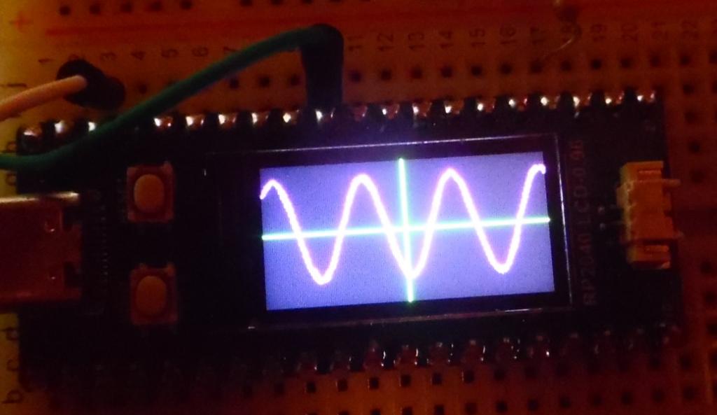
I found a 1KHz sine wave MP3, so here's the waveform played through a 17-year-old iPod. I don't have an external amplifier with adjustable offset, so the ADC only provides values of 0 and greater, clipping the negative voltages. I did have to add a slower timescale, and another vertical scale to get this, but pixels look OK to me. Time to break out the Op Amp Cookbook, or refresh my familiarity with GoldWave. Live in the Future. It's Just Starting Now! |
||||
| phil99 Guru Joined: 11/02/2018 Location: AustraliaPosts: 2136 |
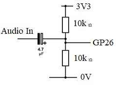
This should do the job.  |
||||
| Mixtel90 Guru Joined: 05/10/2019 Location: United KingdomPosts: 6798 |
Add diodes across the 10k resistors to keep the input between the voltage rails, otherwise you may damage the ADC input. A series resistor of a few hundred ohms might be a good idea (to limit the current through the diodes), but will reduce sensitivity slightly. This is why the clipping diodes are important. With an input of 3V AC peak-to-peak referenced to GND. While the input is at -1.5V the top resistor is charging the capacitor up to 1.5 + 1.65 = 3.15. When the input swings to +1.5V you get a voltage of 1.5 +3.15 = 4.65V applied to the ADC input until the capacitor charge starts to drop. Mick Zilog Inside! nascom.info for Nascom & Gemini Preliminary MMBasic docs & my PCB designs |
||||
| stanleyella Guru Joined: 25/06/2022 Location: United KingdomPosts: 2129 |
NCH-I'm impressed it's plotted. I must try your code, do I need the beta with adcrun? I had probs with pwm test pin .. every pin is already allocated. I tried pins not used > option list PicoMite MMBasic Version 5.07.07 OPTION SYSTEM SPI GP10,GP11,GP28 OPTION AUTORUN ON OPTION LCDPANEL ST7735S, RLANDSCAPE,GP8,GP12,GP9,GP25 OPTION AUDIO GP0,GP1, ON PWM CHANNEL 0 > oops. not ili board but same ie pins not used are used Edited 2023-08-15 03:07 by stanleyella |
||||
| stanleyella Guru Joined: 25/06/2022 Location: United KingdomPosts: 2129 |
Doh I used that for audio > RUN [226] SetPin V_SW, DIN, PULLUP ' Switch to cycle through Voltage scales Error : Pin 1/GP0 is reserved on startup > > ili 480x320 RUN [12] FRAMEBUFFER LAYER L Error : Not enough memory > Edited 2023-08-15 06:40 by stanleyella |
||||
| NPHighview Senior Member Joined: 02/09/2020 Location: United StatesPosts: 200 |
Stanleyella: Sorry to hear that your framebuffer and frame layer are occupying too much memory! I too contemplated using a larger LCD (the Waveshare Pico-Eval-Board) and could only find two non-allocated pins, not enough for front-panel buttons. I never got to the point of breaking into the header connectors, though I was able to observe a shifting "DC" voltage level when I switched the input pin to that of the P-E-B's light-dependent resistor (LDR), and exposed or obscured it with sunlight. I also exposed it to a NeoPixel, which induced a very curious waveform on the LDR. Back on the RP2040-LCD-0.96, I tried out Phil99's RC network (and, through sheer dumb luck got the capacitor polarity right on the first try). The signal shifted up very nicely to the center of the 0-3.3v range. It looked pretty nice using "None" as the triggering type. Unfortunately, your straightforward triggering method no longer worked for rising or falling edges close to zero, so I'm playing with other techniques (getting the min and max of the waveform values, and triggering at the midpoint, either up or down, for instance). I think I'll need to add an "AC-Coupled" setting to get the display centered around the midpoint, and maybe a DPDT switch to include or bypass the RC network. Or, I'll just use it for logic levels :-) By the way, it's been a pleasure collaborating with you in this manner. Edited 2023-08-15 08:21 by NPHighview Live in the Future. It's Just Starting Now! |
||||
TassyJim Guru Joined: 07/08/2011 Location: AustraliaPosts: 6100 |
Runs without any changes on my pico with ILI9341 I did change the background colour so the graticule was visible and there needs to be some scaling adjustments. But, basically, runs well using a standard test finger on the input as a 50Hz signal. I suggest a forced trigger from the console will help. Jim VK7JH MMedit MMBasic Help |
||||
| NPHighview Senior Member Joined: 02/09/2020 Location: United StatesPosts: 200 |
TassyJim - glad to hear it! I was spoiled at an early age with Tektronix and H-P scopes (replacing a dreadful Dumont WWII-era boat anchor I had in 12th grade), and loved the “there but not in your face” graticule coloring. My current 100Mhz dual-channel Tektronix was acquired surplus from nearby UCLA. I’ll post an update when I get min/max triggering working. I think I can use the technique instead of stanleyella’s, but we’ll see. Live in the Future. It's Just Starting Now! |
||||
| stanleyella Guru Joined: 25/06/2022 Location: United KingdomPosts: 2129 |
I changed screen size to 240x240 and not enough memory for layer L ?? |
||||
| Mixtel90 Guru Joined: 05/10/2019 Location: United KingdomPosts: 6798 |
What do you mean by "changed the screen size", Stan? Isn't it set automatically for your display? Const Hres = MM.HRes ' Horizontal screen resolution Const Vres = MM.VRes ' Vertical screen resolution Mick Zilog Inside! nascom.info for Nascom & Gemini Preliminary MMBasic docs & my PCB designs |
||||