|

|
Forum Index : Microcontroller and PC projects : Ready to run PicoMiteVGA for GBP25 - good price?
| Author | Message | ||||
| Mixtel90 Guru Joined: 05/10/2019 Location: United KingdomPosts: 6798 |
Ah, yes - I was taken in by the text positions.... :( The schematic is correct, the board has them reversed. Easy enough to do when you are shuffling the ratsnest around! Mick Zilog Inside! nascom.info for Nascom & Gemini Preliminary MMBasic docs & my PCB designs |
||||
| Calli Regular Member Joined: 20/10/2021 Location: GermanyPosts: 74 |
No problem, most important is that the boards work and they do 4 of 5. I had much fun already. C! Edited 2023-06-10 00:43 by Calli |
||||
| Mixtel90 Guru Joined: 05/10/2019 Location: United KingdomPosts: 6798 |
If those resistors are correct we're looking in the wrong place then. Check the solder joints to the flash chip & clock. Mick Zilog Inside! nascom.info for Nascom & Gemini Preliminary MMBasic docs & my PCB designs |
||||
| Calli Regular Member Joined: 20/10/2021 Location: GermanyPosts: 74 |
* I think all connections around the flash chip are ok, traced all out * Clock... ok, I check, but I was thinking the RP2040 need to run to present me the Firmware update? * Flash has power Next I will poke a bit with the oscilloscope. * Clock Xtal at 12MHz C! Edited 2023-06-10 01:17 by Calli |
||||
| Calli Regular Member Joined: 20/10/2021 Location: GermanyPosts: 74 |
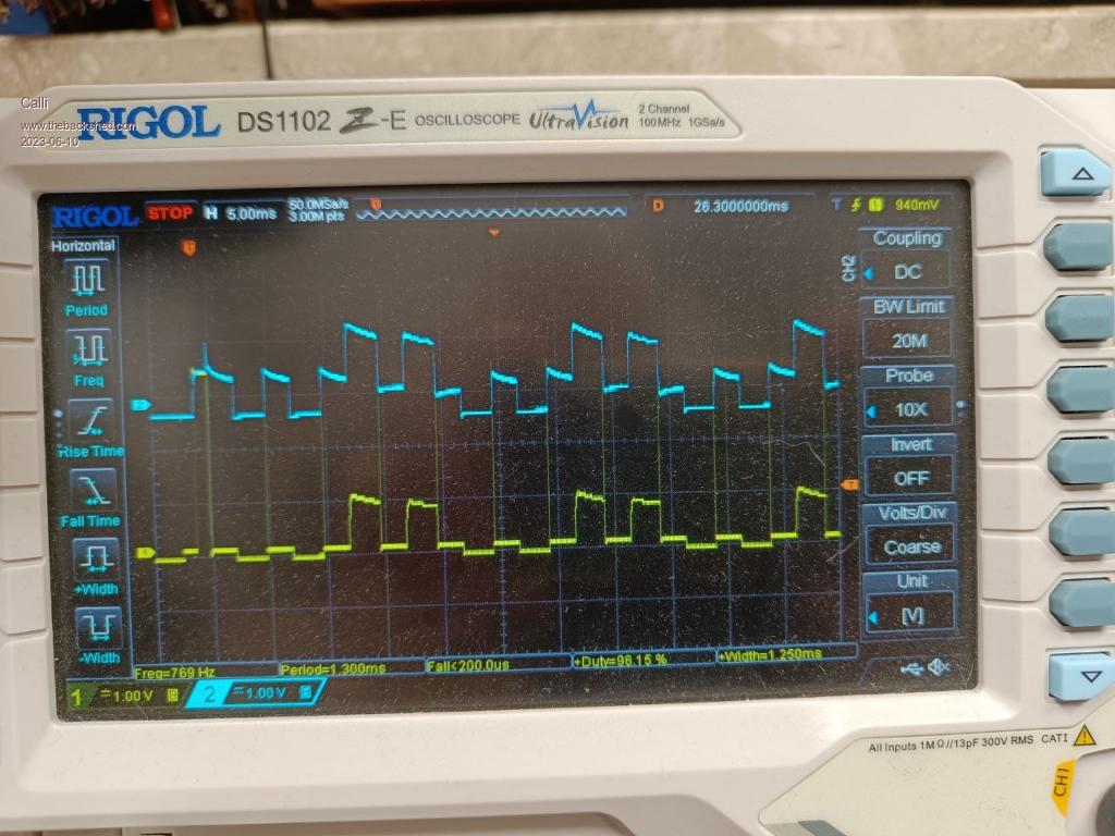
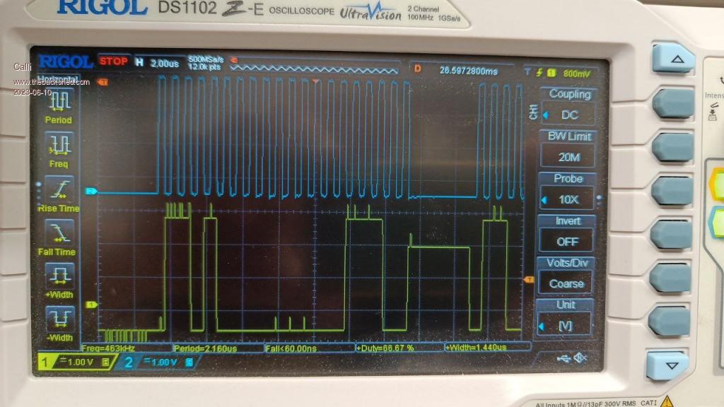
* RP2040 gets a clock * There is activity on the USB lines and I traced them ok * I cant see a proper clock at the flash chip * I can see some activity on DI of the flash when I reset. Hmm clock and DI looks quite strange... Maybe they interfere... (after Reset)  Need to look at a working board. C! |
||||
| Calli Regular Member Joined: 20/10/2021 Location: GermanyPosts: 74 |
Oh yea...  Re-Check the traces around the flash. But not today! Weekend! C! |
||||
| Mixtel90 Guru Joined: 05/10/2019 Location: United KingdomPosts: 6798 |
Often, when you see two different logic voltages above GND it means that a low is fighting a high and you are seeing a half-way level. It's not an analogue system AFAIK. Solder whisker on two pins? Mick Zilog Inside! nascom.info for Nascom & Gemini Preliminary MMBasic docs & my PCB designs |
||||
| matherp Guru Joined: 11/12/2012 Location: United KingdomPosts: 9129 |
I would guess at a short under the rp2040. You could try solderwick with flux all the way round the chip |
||||
| Calli Regular Member Joined: 20/10/2021 Location: GermanyPosts: 74 |
Uhhh. That's all so small 🙄 I was able to look under the flash pins (bino) and thought that looks a bit suspicious. The pads of the rp2040 looked fine never thought there could be a short under the chip. Maybe I try under the flash first an then at the rp2040. If I don't destroy the board my colleague can fix it for me if i fail 😬 Edit: i forgot to mention: best forum ever here 👋 Edited 2023-06-10 06:47 by Calli |
||||
| Mixtel90 Guru Joined: 05/10/2019 Location: United KingdomPosts: 6798 |
Have you got a microscope to examine round the pins? Peter's idea of solder wick and flux sounds good to me, but it's fiddly. It won't draw solder out from the soldered joints themselves but it will suck it out from between the pins. You don't have to be accurate. I usually use a fine solder wick and dip it into liquid flux if I'm trying to clean SMD joints. I must admit that I've never attempted such fine pins as the RP2040 though. Mick Zilog Inside! nascom.info for Nascom & Gemini Preliminary MMBasic docs & my PCB designs |
||||
| Calli Regular Member Joined: 20/10/2021 Location: GermanyPosts: 74 |
Yes I have a old but nice binoculars microscope. Very good stereo image. I try next week I guess. Carsten |
||||
| Calli Regular Member Joined: 20/10/2021 Location: GermanyPosts: 74 |
So! Board works at least to the point where the status led blinks slowly. More tests needed. I first reflowed the contacts where the flash is bound to. I got the clock back. However onto closer inspection today I did see that on the higher pins there was no solder on the pads (legs?) on the RP2040 chip. The pcb pads had solder but it did not flow up to the legs. So I put some solder on and drag soldered then and now it blinks. Thanks for all your help here! Carsten |
||||
| Mixtel90 Guru Joined: 05/10/2019 Location: United KingdomPosts: 6798 |
You're winning. :) Great news! Mick Zilog Inside! nascom.info for Nascom & Gemini Preliminary MMBasic docs & my PCB designs |
||||
| Calli Regular Member Joined: 20/10/2021 Location: GermanyPosts: 74 |
What does this mean? Was there a change between the silkscreen and the PicoMiteVGA, I must admit that I lost a bit the track and using right now PicoMiteVGA MMBasic Version 5.07.07... Cheers, Carsten |
||||
| matherp Guru Joined: 11/12/2012 Location: United KingdomPosts: 9129 |
Page 2 of this thread |
||||
| hhtg1968 Senior Member Joined: 25/05/2023 Location: GermanyPosts: 123 |
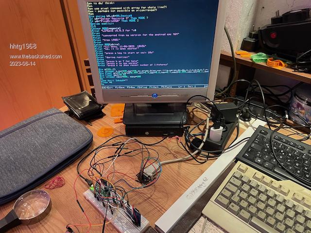
hello. a few hours ago i started my first picomiteVGA! but on breadboard it is only cool for days.  how and where can i order the recent version pcb of matherp (with components)? |
||||
| Mixtel90 Guru Joined: 05/10/2019 Location: United KingdomPosts: 6798 |
The latest versions that matherp got were from JLCPCB. Download the package from Geoff's site - it includes the Gerber files and a bill of materials. Upload those to JLCPCB and choose whatever options you want. If you include the full bill of materials and tell them to assemble it you will get ready built boards. If you like you can delete some of the stuff from the bill of materials to save money - it's a good idea to supply and fit the through-hole components yourself. Note - I personally haven't ordered any of these boards, but I have ordered from JLCPCB several times previously. I think the minimum order is for 5 PCBs and 2 assemblies, so you would get 2 built boards and 3 empty ones. Mick Zilog Inside! nascom.info for Nascom & Gemini Preliminary MMBasic docs & my PCB designs |
||||
| JohnS Guru Joined: 18/11/2011 Location: United KingdomPosts: 3804 |
They're remarkably cheap. I ordered all 5 assembled, 1 didn't work but even so, with a total including s/h under £100, they're incredible value. John |
||||
| Calli Regular Member Joined: 20/10/2021 Location: GermanyPosts: 74 |
Thanks! (I was sure that I did read something about it here in the forum, but searched for wrong keywords) And I am happy that I did found the solution myself. Still can learn in my age.  Cheers, Carsten |
||||
| hhtg1968 Senior Member Joined: 25/05/2023 Location: GermanyPosts: 123 |
Note - I personally haven't ordered any of these boards, but I have ordered from JLCPCB several times previously. I think the minimum order is for 5 PCBs and 2 assemblies, so you would get 2 built boards and 3 empty ones. ok and thank you. i will try to do that... |
||||