|

|
Forum Index : Electronics : Various aspects of home brew inverters
| Author | Message | ||||
Madness Guru Joined: 08/10/2011 Location: AustraliaPosts: 2498 |
Just been going through this topic trying to find answers re generator sync. This generator is what is commonly known as capacitor regulated, it uses a third harmonic winding and a capacitor to power the field. They are okay with things like electric drills but absolutely crap with electronics. Generators with an AVR board rectify AC and feed DC to the field windings and give much cleaner sinewave. There are only 10 types of people in the world: those who understand binary, and those who don't. |
||||
| BenandAmber Guru Joined: 16/02/2019 Location: United StatesPosts: 961 |
warp speed has said something very similar to what you're saying be warned i am good parrot but Dumber than a box of rocks |
||||
| poida Guru Joined: 02/02/2017 Location: AustraliaPosts: 1418 |
Part 35: Gate voltages and MOSFET longevity After the recent blowup of the MAdness power board & nanoverter combo, I am wondering what constitutes OK, best and damaging Gate voltages. The perpetual victim in these stories is the HY4008. Specs say +/- 25 Volts, measured with the Drain as "ground". This is absolute maximum. But what is best, for long life. Maybe the +/-25V is the voltage where HY4008 will survive, for a while. And we need to define "a while" in units of time. Searching around I found a nice paper looking at MOSFET degradation in PV applications and I attach a copy. It's worth a read, in particular for those people here who think Gate voltages don't matter as long as they are high enough. Gate-Driver Parameters Variation and Device Degradation in the PV-Inverter .pdf.zip The important bit:  Here is the high side gate voltage of the Madness power board. It's sort of standard, at least it uses the 18V Zener for high side supply. Once all the high side supply does it's voodoo we can see high side gate voltage peaks at 22.25V Dark Blue is voltage across the 20K Gate pulldown resistor. Light Blue is low side Gate voltage.  I checked the calibration of the Blue trace's probe setup. And it's very good. Now what I have been working at with the previous 32 things I have discussed here is how on Earth we can make these Damnned inverters run for a few years as a minimum. Applying 22.5V to a MOSFET with Vgs specified as +/-25V is skating on thin ice. In the case of the test Madness powerboard I can easily change the 18V Zener to a 15V and things get more better. High side Vgs is now about 18V. I think I will experiment further. wronger than a phone book full of wrong phone numbers |
||||
| BenandAmber Guru Joined: 16/02/2019 Location: United StatesPosts: 961 |
I have some Hy 4008 and even a board if you need it it might be faster than the slow boat be warned i am good parrot but Dumber than a box of rocks |
||||
| poida Guru Joined: 02/02/2017 Location: AustraliaPosts: 1418 |
Part 36: Time to choose the choke core I am building, or have built already and repaired 4 times, inverter #2. If it blows up 4 times in service, I think its not finished yet. So, for the choke I choose to use the Epcos N87 E 70 cores. These are 70 x 32 x 33mm. I bought 2 non gapped cores, one with 0.5mm gap and one with 1mm gap. I wanted to characterise the performance of zero, 0.5 and 1mm gaps. I tested it with the pulse tester, 6 turns of 2mm diameter solid copper enamelled wire and at 16V. I define saturation as where the inductance drops below 1/2 of the linear result. No gap: 33.2 uSec, 1.2A, this is about 440uH. Saturation was at about 5 Amps 6 turns x 5 Amps = 30 Amp.turns 0.5mm gap: (using one zero gap half and the 0.5mm gapped half) 92uS, 19.5A, about 75uH Saturation at about 50A 300 Amp.turns 1.0mm gap: (using one zero gapped and one 1.0mm gapped halves) 98uS, 27.1A, about 58uH Saturation at about 80 Amps 480 Amp.turns. I think I like the 1.0mm gap version, it seems to give me enough headroom before saturation. I only plan to put about 3000W (DC) through it at 50V so that's about 60A DC continuous. I estimate peak current to be about pi/2 x this 60A average. or 95A DC at the peak. (how? integral of sin(x) from 0 to pi is = 2.000, integral of full power( i.e 1.0 ) over 0 to pi, = pi. So the pwm sine wave is not delivering full power for the entire part of the 1/2 sine wave, only at the very top. The power level follows the sine curve shape so I need some average, hence the integral over the 1/2 sine wave, from 0 to pi. And so the pwm is switching current only for 2 units, compared with just switching on for the entire 1/2 of the 50 Hz wave form, just like a 50 Hz square wave. At max output, the sine PWM can only ever deliver 2.0/pi = 0.636 and the 50Hz square wave delivers pi/pi = 1.0. We assume the DC current is "ON" all the time, when in fact it's not. At 100% modulation of the sine PWM, we only are using 0.636 times the possible power compared with a 50Hz square wave) Maybe I need to limit the inverter power or decrease the number of turns on the 1.0m gapped choke. Or put two chokes in series! Another way of looking at this is to look at the case with 100% pwm modulation of the 20kHz PWM. The period of the PWM is 50uS. Let's say we apply 50V across the choke, for 50uS Inductance = (volts x time)/Amps (units are seconds, Volts, Amps and Henrys) Amps = (Volts x time)/Inductance For the 58uH choke, we see (50 x 50E-6)/58E-6 Amps = 43 Amps. Not going to saturate. We need to add about 50A "DC" to this 43 A produced by the 50uS pulse to get an idea of what current the choke is exposed to at 3000W. This is about 90A and just a bit more than the saturation limit. I hope to receive many comments and corrections and that will be good. Edited 2019-09-04 21:51 by poida wronger than a phone book full of wrong phone numbers |
||||
Revlac Guru Joined: 31/12/2016 Location: AustraliaPosts: 1021 |
I have a preference for 2 chokes, and no fear of adding plenty of gap to the second one. Let the second choke do the hard work. I will have to read your post a few more times.  Cheers Aaron Off The Grid |
||||
| Warpspeed Guru Joined: 09/08/2007 Location: AustraliaPosts: 4406 |
The way I would look at this, we have 3Kw load which is about 13 amps rms at 230v in the secondary. If our 48v nominal inverter has say an 8:1 transformer step up ratio, the 50Hz ac current in the primary should be about 8 x 13 amps, or 104 amps rms. The current peak in the primary will be 1.414 times the rms, or lets say 147 amps. The current flowing through the choke will be a 50Hz sine wave, exactly the same as the current flowing through the primary. If the inductance is "sufficient" there should be only a relatively small ripple current at the pwm switching frequency superimposed on our nice clean sine wave. And ripple current will be at a minimum right at the voltage peak anyway, as the duty cycle passes through its highest value right at the peak. So I would be looking for a minimum choke saturation value of something well in excess of 150 amps for the example given. Cheers, Tony. |
||||
| poida Guru Joined: 02/02/2017 Location: AustraliaPosts: 1418 |
Part 37: Low voltage cut off schemes Up until now, I have had my inverter automatically stop running when another controller senses the battery voltage has dropped below a defined set point. I have Navada REC type SLA 12 batteries. I have determined from plenty of tests that what I measure as "48.5V" under zero load and after about 8 hours rest means the battery has about 65 - 70% capacity remaining. I want to cycle these batteries only about 30% or so, no more. And the Navada REC type is supposed to be good for extended times at partial states of charge. Anyway, up until a few weeks ago, I had my system controlling the inverter in such a way to stop it once 48.5V was achieved. Some days I get more sun that others so the run time for inverter might be many hours longer. Or shorter. Some days my son has his mates over for a huge xbox/pizza evening. And I see rather shorter inverter run times for that those nights. When the inverter stops, the automatic change over relay switches the power source immediately over to street power, and stays there until the battery exceeds 51V the following day during the morning's charge and the inverter automatically restarts. I found that the LV cutoff of 48.5V was a good "overall" choice. It kept the battery safe from over discharge. But some times there are large loads present, dragging the battery voltage down, even when the capacity is 80%. Then LV cutoff is executed and I did not use the full 30% of charge I could have for that evening. I know, I know, I should use 1 inch thick copper cable everywhere. I do not. So there are voltage drops due to high loads. Now I have a scheme in place that takes the DC current and modifies the LV cutoff voltage, each time the calculations are run (every 2 minutes) The scheme is: for DC loads less than or equal to zero Amps, LV cutoff = 48.5V For loads greater than zero and less than 20 amps, linearly interpolate LV cutoff from 48.5V to 47.5V, where 0A = 48.5V and 20A = 47.5V For loads greater than 20 Amps, just set LV cutoff = 47.5V This permits the system to keep running for longer periods, in my case extending inverter run times on some nights for 4 hours or more than before. (when the xbox was running hot & my wife was printing something on the laser printer at the same time, the current would be huge and prematurely cause the inverter to stop for the night. Not any more.) Below is a graph of the battery voltage, DC load due to inverter and the LV cutoff in effect at each of the time intervals. Black is LV cutoff, Orange is DC power (or current, divide by battery voltage) Blue is battery voltage.  I like the way this works and so it means I now have to disable the LV cutoff function in the nanoverter, so as to implement it in the raspberry Pi controller code where I have much more control over it's performance. The nanoverter of mine does not have DC current sense capability at this time. I expect further tuning of this LV cutoff scheme as the seasons change and I learn further how it performs. Edited 2019-09-18 21:07 by poida wronger than a phone book full of wrong phone numbers |
||||
| poida Guru Joined: 02/02/2017 Location: AustraliaPosts: 1418 |
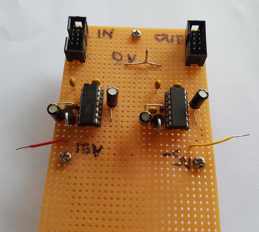
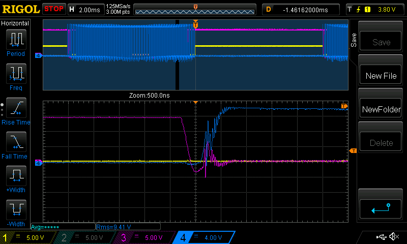
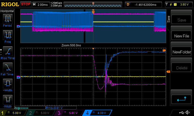
Part 38: Negative DC bias on gate drive voltage Yesterday I built this:  It permits me to put a -5V bias on the gate drives. Instead of having "off" as 0V and "on" as 15V, it's now "off" = -5V and "on" = 15V. I have been obsessed with shoot through and I want so see if when I pull the low side gates down -5V, do things improve? The above board takes the output of the nanoverter (or Madness control board) and uses those outputs as inputs for a pair of IR2110 ICs. Simply use the 10 pin ribbon cable plugs. Change over from using it to straight through takes 10 seconds. I feed the IR2110 with a -5V offset on the low end of their output stages and things work well. I used this circuit exactly. I think I might need something smaller than 100K on the Pin5 (Vs) but anyway..  obtained from here I see the worst effects of shoot through at locations near the beginning and end of the 1/2 cycle of the AC output. I look at 1.5 ms before the end or zero crossing of the AC output. Pink is LOW side gate voltage (i.e. Vgs), Dark Blue is HIGH side gate voltage 200 W load, the exact same PWM cycle in both cases. 50V DC supply, standard toroid and choke.. No negative offset:  Bad oscillation of both gate voltages indicating shoot through and uncontrolled short circuit of the DC bus, but only for a short period of time. Now with -5V offset:  Certainly the oscillation remains. Bugger. It did not cure it. But it did pull the low side Vgs down 5 V below low side's Source... The oscillation amplitude has increased a lot and maybe this is due to the inductance of the now 2 lengths of ribbon cable? And ground loops? Anyway, it's food for thought and that means I'm going for a walk and a think. wronger than a phone book full of wrong phone numbers |
||||
| Solar Mike Guru Joined: 08/02/2015 Location: New ZealandPosts: 1138 |
Poida, when the low side gate drivers are turned off, think of them as being a short or very low impedance across the gate input, the higher rated (for drive current) the lower this is. At the point of hi side turn on, the low side mosfets are subject to very fast rise time drain voltages that get reflected back across the gate input by the miller effect capacitance within the mosfet. Now the low side gate circuit has an effective short across it, but located some distance away at the driver chip, ie at the end of an inductive length of wire, thus the extensive gate ringing you observe on your scope. To minimize this, place the gate driver close as physically possible to each mosfet, this keeps the lumped inductance down; also add a small resistance into the circuit to act as a damper to the oscillation currents reflecting back and forth between the gate and driver (1-5r). None of this is easy to retro fit to an existing layout unfortunately; however if you arrange for the low side mosfets to switch at the 50 hz rate, then add a small capacitance (10,000pf) across the gate to source (distributed between the number of mosfets in parallel); the effect is to partially absorb the very short ringing spikes, noting that the driver chip will have to work harder to charge and discharge this extra capacitance and will slow the turn on\off a little (should be ok at 50 hz though), depends on the driver chip being used. Welcome to the world of RF circuit engineering.... Cheers Mike |
||||
| poida Guru Joined: 02/02/2017 Location: AustraliaPosts: 1418 |
Thanks Solar Mike. I need all the help I can get with this. I think the above description you give is a good start in the story of what is happening. wronger than a phone book full of wrong phone numbers |
||||
| Solar Mike Guru Joined: 08/02/2015 Location: New ZealandPosts: 1138 |
You should be able to reduce the high side ringing by fitting a suitable snubber RC across the Drain\Source, google will tell you how to work out the RC values. You can measure the ringing frequency on your scope. Reducing that may also reduce the reflected ringing on the low side gate circuit. Cheers Mike |
||||
| wiseguy Guru Joined: 21/06/2018 Location: AustraliaPosts: 1156 |
Poida, what value gate resistor are you using in series with the driver ? If too high, fast dvdt on the drain will/can try to turn on the FET briefly. As Solar Mike says keeping series resistance and inductance loops as short as possible definitely helps. It looks like the upper side gate drive voltage is turning on the upper side FET, this pulls the lower side FETs drain rapidly high and cdg couples this back to the lower FET's gate causing the shoot through glitch. Having a gate clamp transistor right at the gate or lowering the gate drive inductance/resistance should minimise the effect. Is there just one FET in each of the bridge legs - the oscillation you are getting looks very similar to what I have seen before when there is more than 1 FET per leg. I forgot to mention, if you are not using a diode across the gate resistor (cathode facing away from the gate) it can help a lot by being a much lower impedance when the driver is driving the gate off, to counteract the parasitic dvdt turn on. In theory it should clamp the gate at 0.7V with no resistor in series with the diode. However circuit inductance and resistance can still work against you. Also with no resistor in series with the gate diode, the FET turn off speed may be increased to the point where it starts to become problematic too, so some juggling of values may be needed. Edited 2019-09-26 10:25 by wiseguy If at first you dont succeed, I suggest you avoid sky diving.... Cheers Mike |
||||
| noneyabussiness Guru Joined: 31/07/2017 Location: AustraliaPosts: 512 |
Hey Poida, is there any trick to getting this to sync?? Ive fed a clean 50hz 12v signal to the opto (as per the schematic) and it doesn't seem to want to activate the external relay .. I can activate the external relay via the 680ohm resistor directly, so thats working and there is a clean 5v 50hz pulse going into d2 on the nano... what am i doing wrong ?? Thank you so much again in advance I think it works !! |
||||
| noneyabussiness Guru Joined: 31/07/2017 Location: AustraliaPosts: 512 |
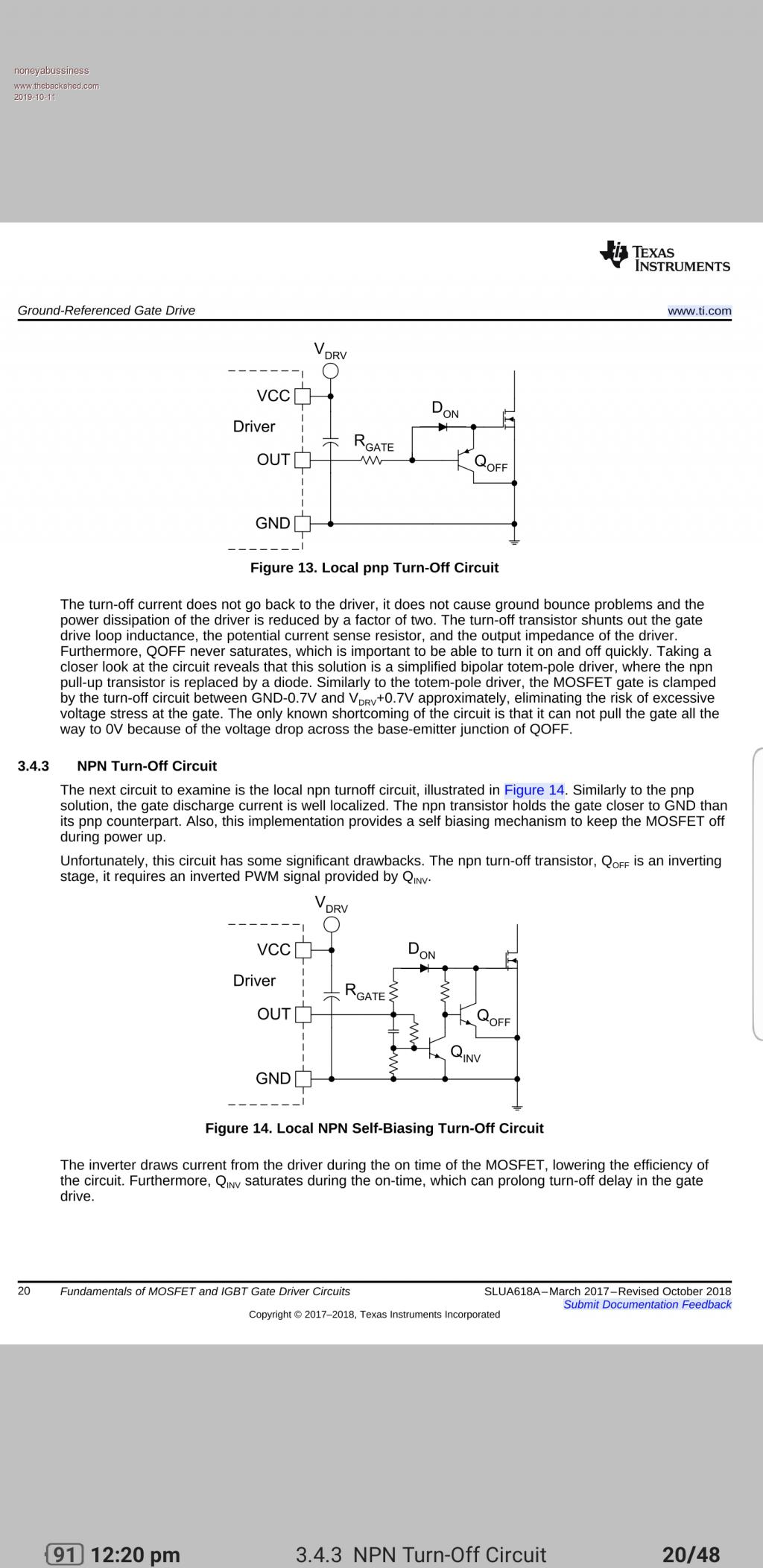
 Oh and maybe something like this for EACH mosfet, figure 13.. may help dv/dt as it shorts it at the mosfet instead of back to the driver...easy to implement in current guise as its a diode and a pnp... I think it works !! |
||||
| noneyabussiness Guru Joined: 31/07/2017 Location: AustraliaPosts: 512 |
 Don't know what happened to pic, ill try again.. I think it works !! |
||||
| noneyabussiness Guru Joined: 31/07/2017 Location: AustraliaPosts: 512 |
Ok , pics are not working for some reason, its figure 13 on Texas Instruments app note SLUA618A... it will pull down individual mosfets to ground AT the source pin, so as to avoid the driver to mosfet gate inductance... just a thought... I think it works !! |
||||
| noneyabussiness Guru Joined: 31/07/2017 Location: AustraliaPosts: 512 |
Never mind about sync question, turned out to be a dodgy relay.... ugh, sometimes i wonder.. I think it works !! |
||||
| noneyabussiness Guru Joined: 31/07/2017 Location: AustraliaPosts: 512 |
Ok , belay last, turns out you have to call " pinmode (4, OUTPUT) " on my ide in "setup " for the pin to actually work... wouldn't run a relay only the led until i did this... Hope this helps anyone in future, Tinker, was the relay and led lighting up properly on yours when you tested it ?? Before i added that line, under any load to pin it would just drop out ( to base of npn with 220 ohm resistor .7v , as soon as relay connected, 0v).. I hope my ramblings make sense I think it works !! |
||||
| noneyabussiness Guru Joined: 31/07/2017 Location: AustraliaPosts: 512 |
Ok.. spent a good few hours going through different combinations of inductors and even resistors, filters of every imaginable sort... to get this thing to sync and hold... it just kept drifting and drawing current, cause all sorts of issues... given up for now, sorry poida, i tried.. I think it works !! |
||||