|

|
Forum Index : Electronics : Started Buck converter project
| Author | Message | ||||
| govertical Guru Joined: 11/12/2008 Location: United StatesPosts: 383 |
Hi, I think I understand what you saying regarding the difficulties for using the SEPIC topology. Would using a variable frequency generator help achieve SEPIC circuit resonance when driving the mosfet gate? just because your a GURU or forum administer does not mean your always correct :) |
||||
| Warpspeed Guru Joined: 09/08/2007 Location: AustraliaPosts: 4406 |
There is no resonance in the SEPIC topolgy, no sine waves anywhere..... It is all about inductors storing and releasing packets of energy, and it will be vastly more complex to design and get going than a simple buck regulator. Cheers, †Tony. |
||||
| govertical Guru Joined: 11/12/2008 Location: United StatesPosts: 383 |
Hi, I found another reference paper that shows a buck converter using a isolated power supply for the gate driver to drive a N channel mosfet for a battery charging circuit. Chapter 4. page 69 http://etd.ohiolink.edu/view.cgi?acc_num=akron1320692738 I do not understand how using a gate driver with a isolated voltage will work without a bootstrap capacitor configuration, or are they two different methods? Comments welcome just because your a GURU or forum administer does not mean your always correct :) |
||||
| Warpspeed Guru Joined: 09/08/2007 Location: AustraliaPosts: 4406 |
You need a totally isolated power source for the gate drive circuit of a buck regulator. Only three ways to do it. 1/ A battery that will need frequent replacement. 2/ A fully isolated dc supply from some kind of fully isolated switching power supply. 3/ A charge storage bootstrap capacitor that is recharged via a diode every time the buck regulator turns off. I am becoming a bit tired of all this. Cheers, †Tony. |
||||
| govertical Guru Joined: 11/12/2008 Location: United StatesPosts: 383 |
Hi, I understand. Your assistance is greatly appreciated. When I started this project I had no experience with power electronics. With the limited success I have experience and all the reference material I have found I should be able to fabricate a working circuit. What really impresses me is how much this type of circuit can improve turbine performance and output. I will post working circuit and test results when available. Thank again and enjoy the summer. just because your a GURU or forum administer does not mean your always correct :) |
||||
| govertical Guru Joined: 11/12/2008 Location: United StatesPosts: 383 |
Hi, I have verified that using a isolated power supply for the gate drive circuit will turn the N channel mosfet on and off in a Buck circuit configuration with a 12 volt battery as a load. I configured the gate drive circuit with a 555 time and used a Schmitz triggered nand gate as a inverter. The 555 timer was configured with a variable 1 meg ohm pot so the duty cycle could be changed. The shorter I set the duty cycle the easier the PMA was able to spin and produced a very high voltage at Vin. Positive current was flowing into the battery. Under manual operation the best I could achieve was 0.7 amps flowing into the battery. The circuit will definitely benefit from using a microcontroller to adjust the duty cycle. At this time I am starting to work on paralleling the mosfets and adding a microcontroller to the system. Comments welcome just because your a GURU or forum administer does not mean your always correct :) |
||||
| govertical Guru Joined: 11/12/2008 Location: United StatesPosts: 383 |
Side note: I replaced the battery with the 50 watt halogen and was unable to illuminate the light. I was expecting to able to reproduce the earlier results but I was not. Not sure why. just because your a GURU or forum administer does not mean your always correct :) |
||||
| govertical Guru Joined: 11/12/2008 Location: United StatesPosts: 383 |
Hi, I have verified that using a isolated power supply for the gate drive circuit will turn the N channel mosfet on and off in a Buck circuit configuration with a 12 volt battery as a load. I configured the gate drive circuit with a 555 time and used a Schmitz triggered nand gate as a inverter. The 555 timer was configured with a variable 1 meg ohm pot so the duty cycle could be changed. The shorter I set the duty cycle the easier the PMA was able to spin and produced a very high voltage at Vin. Positive current was flowing into the battery. Under manual operation the best I could achieve was 0.7 amps flowing into the battery. The circuit will definitely benefit from using a microcontroller to adjust the duty cycle. At this time I starting to work on paralleling the mosfets and adding a microcontroller to the system. Comments welcome This is the part I find confusing: When comparing the waveforms of the two gate driver circuitís the circuit without the IR2117 triggers the mosfet all the time. Video without IR2117 in gate driver circuit: mosfet Vs is top waveform: without IR2117 The circuit using the IR2117 only triggers the mosfet when the PMA provides a input voltage. Video using IR2117, bottom waveform is mosfet Vs: using IR2117 Waveforms in both videos are measured at the same point. just because your a GURU or forum administer does not mean your always correct :) |
||||
| govertical Guru Joined: 11/12/2008 Location: United StatesPosts: 383 |
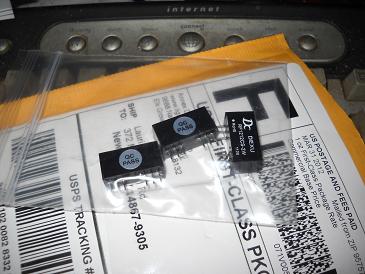
Greetings, isolated power supply modules have arrived. Hopefully this will prevent the 555 timer from shutting down when a 12 volt battery is used as a load. I did some informal experimenting and noticed that very small changes of the duty cycle control signal had dramatic affects on the required torque for the PMA under manual operation. 
just because your a GURU or forum administer does not mean your always correct :) |
||||
| govertical Guru Joined: 11/12/2008 Location: United StatesPosts: 383 |
Greetings, using a isolated power supply and FOD3180 does work. I am using a blocking diode between the inductor output and the plus terminal of the 12 volt battery. The gate driver is triggering a N channel IRF540 in a Buck circuit configuration and is charging the battery, current about 1 amp. Then I replaced the battery with the 50 watt halogen light and the circuit was able to illuminate the light after I adjusted the duty cycle, current max about 4 amps. I was manually operating the PMA. So far this is a very happy day. The next step is to drive the PMA with the drill press to determine how the circuit behaves at a higher RPM. Chapter 4. page 69 http://etd.ohiolink.edu/view.cgi?acc_num=akron1320692738 Isolated power supply with FOD3180 gate driver. N channel Buck converter using a IRF540 mosfet. Bottom wave form is gate of mosfet, top wave form is source of mosfet. Input voltage max about 40 volts. Output current varies depending on duty cycle. Circuit still needs improvement but it is working. Input voltage is from a permanent magnet alternator and is being manually operated. Comments welcome. Gate and Source Waveform just because your a GURU or forum administer does not mean your always correct :) |
||||
| Warpspeed Guru Joined: 09/08/2007 Location: AustraliaPosts: 4406 |
Now that you have a constant dc supply voltage to the isolated gate driver, you can ditch the battery blocking diode. Next thing will be to either increase the operating frequency well above the 5Khz you are getting out of the 555, or fit a much higher inductance choke to the buck regulator. With such a low switching frequency, and very small air cored choke, all you are really doing is shorting the PMA directly across the battery for brief periods of time while the MOSFET turns on. It will not be operating as a true buck regulator. There will be some very high peak currents through the MOSFET the way it is operating now, which is neither safe (for the MOSFET) or efficient for higher power operation. Cheers, †Tony. |
||||
| govertical Guru Joined: 11/12/2008 Location: United StatesPosts: 383 |
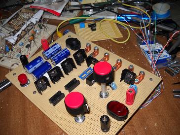
Hi, working on perf_board ciruit layout. Configured 50 volts caps at input to form a 1000uf at 100 volts. Not sure how well it will work. Rotary switch varies duty cycle from 10% to 50%, using 5 k potentiometer so each fixed percent value has small variable adjustment. Results of earlier testing revealed if there was a voltage stored at Vin the mosfet would not turn on. I added a reset discharge switch to address the problem. I am using 4 IRF510ís in parallel just for the experience. I am trying for 15 amps max output. Added 7812 for Vcc to IC's and isolated power supply source. I am including test points to try to verify Buck converter operation. Hopefully testing in a few days. 

just because your a GURU or forum administer does not mean your always correct :) |
||||
| govertical Guru Joined: 11/12/2008 Location: United StatesPosts: 383 |
Hi, I completed fabrication of analog MPPT test circuit. Video shows verification of selectable duty cycle with fine adjustment of each for each selected duty cycle, 10% to 50%. Next step is to test with PMA and battery test load. I am hoping I did not damage the mosfets when I solder them in the circuit. FOD3180 output for analog MPPT test circuit just because your a GURU or forum administer does not mean your always correct :) |
||||
| Warpspeed Guru Joined: 09/08/2007 Location: AustraliaPosts: 4406 |
That looks excellent !! What frequency are you running the PWM ? Cheers, †Tony. |
||||
| govertical Guru Joined: 11/12/2008 Location: United StatesPosts: 383 |
Hi, I finally found and attached all the connectors to make the all the measurements and I found out I have to charge the battery that I am using for a test load. I am using a 7812 to supply Vcc for ICís and the test load is the power source. I sure you can appreciate the irony, it is always the little things. 
Switching frequency is 20kHz. I can change the inductor and the switching frequency without to much trouble. I should be testing in the morning. Cheers 
just because your a GURU or forum administer does not mean your always correct :) |
||||
| govertical Guru Joined: 11/12/2008 Location: United StatesPosts: 383 |
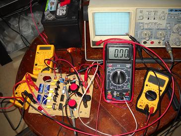
Hi, just a quick video showing test setup. With the PMA at 200 RPM the input voltage was 170 volts, 1.5 amps input current, 12.34 output voltage, and 0.3 output current. Mosfets measured 82 degrees Fahrenheit. The circuit needs major improvements. The input capacitor is only rated for 100 volts and I have to check my inductor calculation. So there are major loses and the buck circuit is not working as it should but the test fixture is working. I am using a 12 volt deep cell for a test load. It does show the control circuit is working and the mosfets are turning on and off. It is a start. Comments welcome. Test fixture just because your a GURU or forum administer does not mean your always correct :) |
||||
| Warpspeed Guru Joined: 09/08/2007 Location: AustraliaPosts: 4406 |
The problem most likely is that the buck inductor has far too little inductance. Another possibility is the input reservoir capacitor is too small. What I suggest you try is placing a current measurement shunt in the negative side of the battery to look at the battery charging current. It should be a sawtooth ripple current waveform sitting on top of a continuous dc charging current. The amplitude of the sawtooth ripple is directly proportional to the inductance of the choke. An infinite inductance would give a perfectly constant dc charging current, but that is not going to happen. Zero, or too little inductance will produce massive current pulses through the MOSFET, falling to zero current during the "off" periods. Maximum peak to peak ripple amplitude will always occur at 50% duty cycle. Cheers, †Tony. |
||||
| govertical Guru Joined: 11/12/2008 Location: United StatesPosts: 383 |
Hi, new data from test fixture. Vin 30 vdc Iin 0.5 Idc 15 watts at the input Vout 12.32 vdc Iout 2.3 Idc 28.3 watts at the output Circuit operating at 30kHz @ 50% duty cycle. PMA RPM 160 mosfet temp 82 degrees Fahrenheit The data is just ballpark values. I am confused by results. There should be a lost of power not a increase. I may have a problem with multi meter reading current at the input. It would make more sense if the input current was about 1 amp. The meter is a cheap-O. The variable duty cycle switch does appear to be working. There is a lot ringing in the waveform. I have to improve the inductor and reduce the voltage spikes. Comments welcome just because your a GURU or forum administer does not mean your always correct :) |
||||
| Warpspeed Guru Joined: 09/08/2007 Location: AustraliaPosts: 4406 |
How do you get 28 watts out for only 15 watts in ? There has to be an error in that somewhere. Cheers, †Tony. |
||||
| govertical Guru Joined: 11/12/2008 Location: United StatesPosts: 383 |
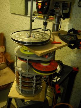
Hi, I did some investigating today and found that two of the meters are not working correctly and a some intermittent contacts. I have to purchase some new meters. I also added a idler pulley to the belt drive to stop the belt from slipping at the drill press. I should know more in a few days. One good thing to report is that no parts on the circuit have been damaged. No smoke, no funny smells. Can you suggest a good value for the input capacitor? The I am using now is over sized and very expensive. 7800 uF @ 125 volts just because your a GURU or forum administer does not mean your always correct :) |
||||