
|

|
Forum Index : Microcontroller and PC projects : SMALL UPS...
| Author | Message | ||||
| Volhout Guru Joined: 05/03/2018 Location: NetherlandsPosts: 4223 |
Hi Grogster, I would investigate looking into the datasheet of the cable. It will show to what standard the cable is tested. Using an insulation tester is risky since when it arcs you essentially lost a cable (at least that pair, but maybe adjacent as well). You can use the Impedance test function at 500V, but since you know it is a telephone cable, with 48V nominal, and 90V ring voltage, a test voltage of 500V may even be too much. But testing every pair to be used at 100V should be okay, and even advisable. Volhout PicomiteVGA PETSCII ROBOTS |
||||
| Mixtel90 Guru Joined: 05/10/2019 Location: United KingdomPosts: 6781 |
I'm not sure about 1000V on telephone pairs, but most wire will easily take 3x the working voltage that it's normally used for, in my experience. :) That's why I suggested 250V. 3x the 90V ringing voltage isn't far off. One has to live *just slightly* dangerously to have a bit of fun. :) DO NOT clamp one tab of an OC35 in a vice, connect the vice to neutral then dab live onto either the base or emitter. They go bang and the top flies off at very high speed, embedding it into the wall. NEVER, EVER DO THIS, girls and boys. It's dangerous. :) (Yes, I've watched it being done!). Mick Zilog Inside! nascom.info for Nascom & Gemini Preliminary MMBasic docs & my PCB designs |
||||
Grogster Admin Group Joined: 31/12/2012 Location: New ZealandPosts: 9306 |
Hey, Volhout, and happy to see you post again. I had a sudden thought that my "No no no" post might have been offensive to you - certainly not my intention, but I did think about that today!    @ Mick: Yeah, I must admit I never ACTUALLY tested at 1000v - that was just what the mega was capable of doing. I would test at 250v, and if that was suspicious in terms of insulation breakdown, I would test at 500v. Nine times out of ten, if the 250v test was suspicious, then the 500v test would show total breakdown, so that pair was taken out of service, marked as "Faulty" in the records, and the service in question was transposed to another good pair. Sorry to all of you reading this, not really familiar with the telephone cable faults lingo!  Crikey!   Ah....no - don't do that! EDIT: I will see if I can find the old mega I used to use, and I will post details and a photo here if I find it. Edited 2024-06-18 17:56 by Grogster Smoke makes things work. When the smoke gets out, it stops! |
||||
Grogster Admin Group Joined: 31/12/2012 Location: New ZealandPosts: 9306 |
UPDATE: I finally got around to looking into hacking these amps, so that I can power them from a LV DC supply, rather then trying to get 230v to work over the phone lines. I took apart the spare Televes amp today - it is BEAUTIFULLY built, and built like a brick privy!!! Take off the decal on the front, reveals the screws holding the diecast aluminum case together - 62 small machine screws! ...and that's JUST to get the lid off, so I could peek inside!  SMPS is simple single-rail 12v DC supply - yay! Current consumption is 540mA @ 12v continuous, which I would expect for a TV amp. That should be really easy to deal with either via a linear drop-down regulator arrangement, or perhaps a buck converter, as the original PSU inside the thing, is a SMPSU anyway. If I simply remove the internal SMPSU, there is then plenty of room int there, to easily fit some form of 12v PSU, which I can then feed from either 24vAC or 36vAC via the redundant phone pairs. I attach some photos. 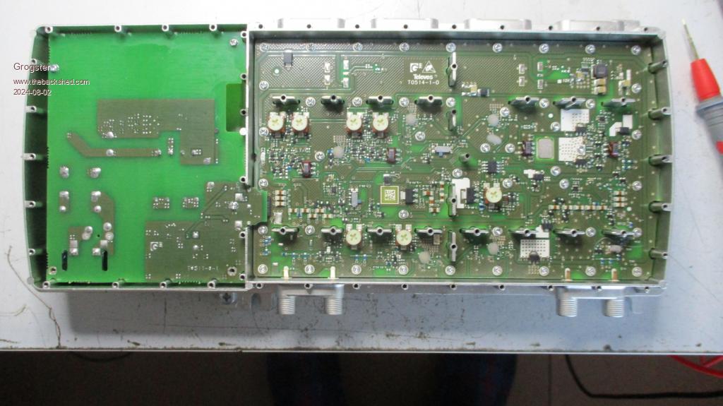 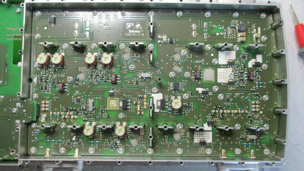 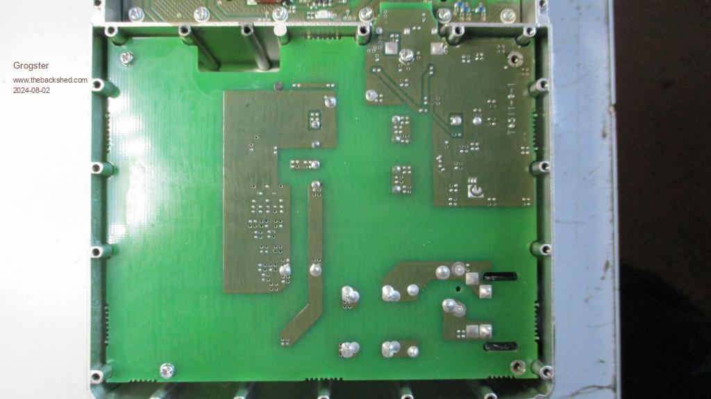 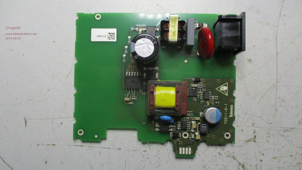 Smoke makes things work. When the smoke gets out, it stops! |
||||
Quazee137 Guru Joined: 07/08/2016 Location: United StatesPosts: 567 |
Grogster what about using 4 cells and a solar charger? I guess it depends where and how you mount these. A small cheap backyard solar light with batteries could be repurposed. My HOA replaced hardwired 120VAC lights with the solar after the AC lines got ripped up by local gas co trying out the horizontal boring to replace very old gas lines. If they open up the roads they have to replace them so they are looking to go cheap. Quazee137 |
||||
Grogster Admin Group Joined: 31/12/2012 Location: New ZealandPosts: 9306 |
Another nice idea - I will take it under advisement.  The main issue with that, is that these amps are inside access boxes on the side of the house, and so when the box is closed, there is no way for a solar panel to work, as it will be dark. Sure, we could install one for each box, but I think that would involve more work then using the old phone cables. And the residents might complain about the visibility of the solar panels.  Smoke makes things work. When the smoke gets out, it stops! |
||||
| Mixtel90 Guru Joined: 05/10/2019 Location: United KingdomPosts: 6781 |
That's some very nice construction indeed! Mind you, VHF/UHF construction generally looks very cool. :) You may still need a bit of a kick current-wise for it to fire up. Have you got a multimeter with max hold on it? It might be that the switch-on surge is only in the PSU. Mick Zilog Inside! nascom.info for Nascom & Gemini Preliminary MMBasic docs & my PCB designs |
||||
| Volhout Guru Joined: 05/03/2018 Location: NetherlandsPosts: 4223 |
Hi Grogster, Looking at your photo's I notice few things on this power supply. 1/ There is 1 large electrolytic cap, which is after the secondary rectifier. But no inductor of any size, and second capacitor. 2/ There are 3 SO8 (2 nomal, 1 SO8-wide) chips in the secondary side of the power supply. Since TV amplifiers must amplify AM modulated signals with high dynamic range, the 12V bus must be clean of any ripple and noise. So I expect that there is a 13.6V power supply, followed by a 12V linear regulator (in SO8 ?) or alike. 3/ There are 2 large test pads in the secondary side, potentially for measuring the 12V (or 13.6V), but also 3 smaller test pads exactly where the power supply passes the aluminum wall to thr RF circuit. That would be a sign of 3 signals going to the analog circuit. One of them is most likely ground, the other 12V. But what is the 3'rd. Is it a "power good" signal, or a +30V, or +5V....? In case you plan to replace the power supply with your own design. Make sure there is an isolation between input and the 12V output. You do not want the telephone ground cable to be hard connected to the coax cables in the TV system. That would present horor ground loops all over the area. So you need a transformer based dc-dc convertor. Regards, Volhout P.S. Why replace the current PSU ? You work around the telephone line plan. The load is 12V 540mA = 6.5 watt, assume 7 watt. Since you have to work in the capabilities of the telephone line you can make a curve of volts/amps you think the telephone line can handle. There will be a peak (where the line can transfer most power) and that will be close to the maximum voltage you think you can apply to the line. That is not 12V 24V or 36V, but rather 48V or even 90V. Can the built-in power supply work at that voltage ? When it can't, isn't it simplet to replace the bridge rectifier to a voltage doubler (need an extra E-cap), and drive the power supply with 60Vac or so... from the telephone line... Just thoughts. Edited 2024-08-02 16:52 by Volhout PicomiteVGA PETSCII ROBOTS |
||||
Grogster Admin Group Joined: 31/12/2012 Location: New ZealandPosts: 9306 |
Hi chums. I attach some more photos, and a close-up of the PSU output. 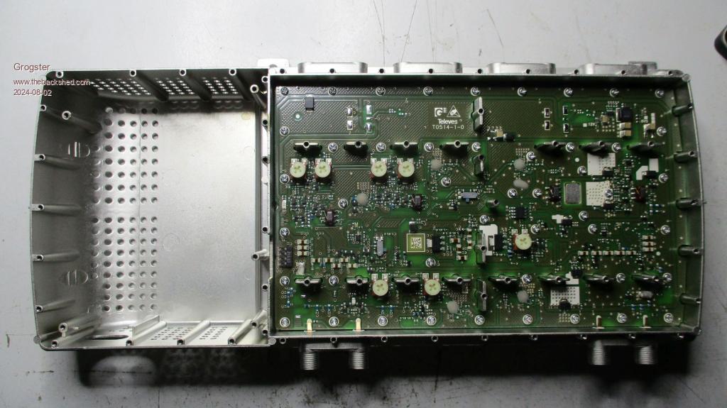 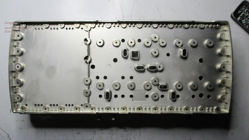 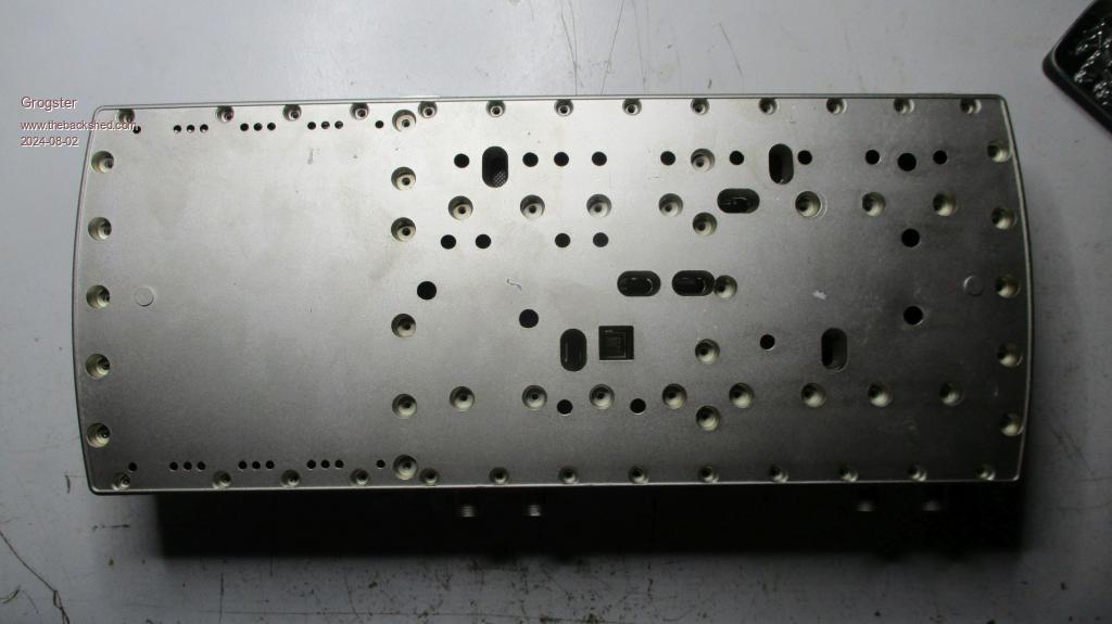 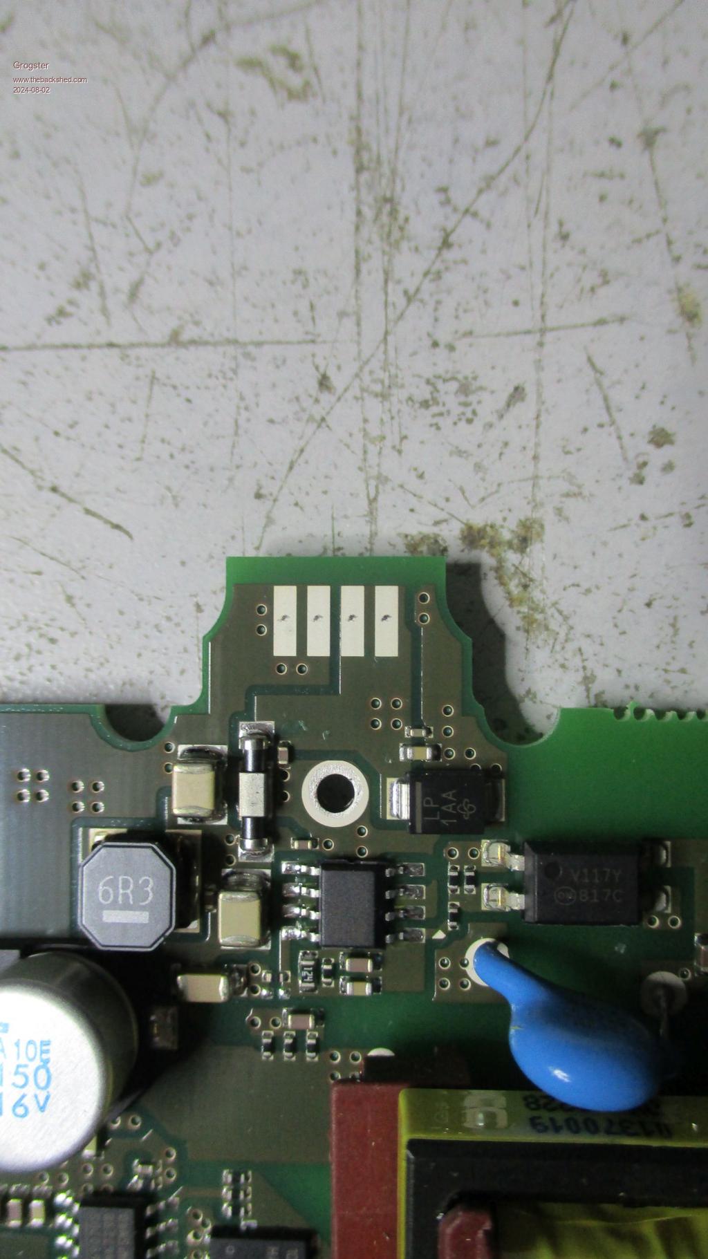 Excellent point. Thanks.  Smoke makes things work. When the smoke gets out, it stops! |
||||
| Volhout Guru Joined: 05/03/2018 Location: NetherlandsPosts: 4223 |
Aha, It has a post regulator (switching) to create 12V. And it is just 12V going to the RF circuit. Volhout PicomiteVGA PETSCII ROBOTS |
||||
Grogster Admin Group Joined: 31/12/2012 Location: New ZealandPosts: 9306 |
As I am MOST LIKELY going to want to look at putting in my own LV regulator thing for these amps, do you happen to have any recommendation for a 12v ground-isolated SMPSU module or circuit perhaps? I most DEFINELTY do NOT want ground loops from the LV DC to the coax shields.  Smoke makes things work. When the smoke gets out, it stops! |
||||
| Volhout Guru Joined: 05/03/2018 Location: NetherlandsPosts: 4223 |
This would suffice to run the PSU from 50Vac... 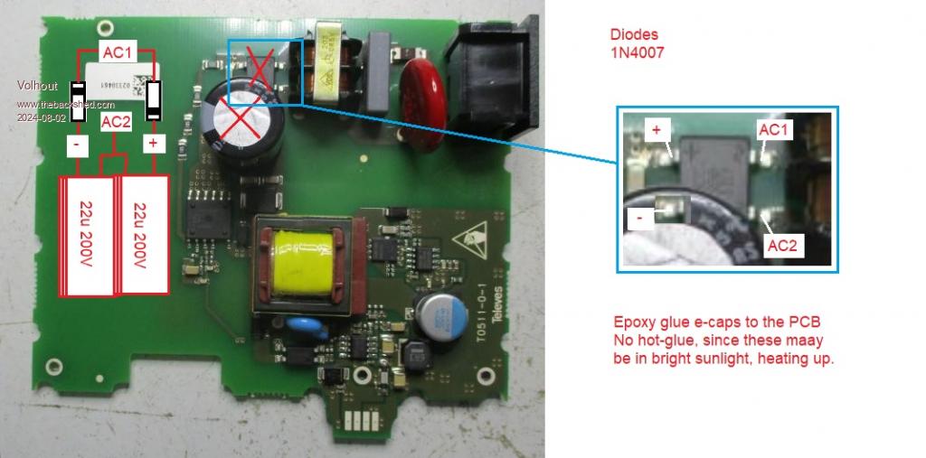 You could even leave the E-cap on the board, just add 2x E-cap and 2x diode, and replace the bridge rectifier. Since the ripple in a voltage doubler results in half 2x half rectification, the ripple changes from 100Hz to 50Hz. Meaning that leaving the original e-cap on the board may be very useful. After breadboard testing it, you can also make a PCB that holds the voltage doubler, and leave a more professional impression to the customers. Volhout Edited 2024-08-02 17:20 by Volhout PicomiteVGA PETSCII ROBOTS |
||||
| Volhout Guru Joined: 05/03/2018 Location: NetherlandsPosts: 4223 |
DC-12C isolated 48V-12V isolated A suggestion from me: try to find (Aliexpress of Farnell or the likes) a second type convertor. Preferably a well-know brand such as Murata, Recon or Pulse so. Make a layout that supports both footprints. Just in case one becomes obsolete, you can always polulate the second one (even if it is more expensive). It may take a year before all systems are converted. And you don't want to stop half way becuase you have to redesign. Note: in the Televes they have PolyFuse in the inptu circuit. Not a normal fuse. In many cases the PolyFuse recovers after the fault is gone, and you may not have to send out the repair team (yourself  ). ).Volhout Edited 2024-08-02 17:33 by Volhout PicomiteVGA PETSCII ROBOTS |
||||
Quazee137 Guru Joined: 07/08/2016 Location: United StatesPosts: 567 |
What is the min AC line voltage in? I have used power supplies with a wide range of input as low as 60VAC to 240VAC. What might you get feeding 60VAC in? If need be may be a mod to the AC input circuity to lower the needed 240VAC to something you can use. I have used a lot of the USB 5VDC power boards taking 95VAC to 250VAC. In some locations the water towers had only 250VAC others 120VAC. The power modules saved me from needing two types of 5Volt supplies. Funny I do think they where universal USB UK,AU,NZ or USA,Japan without housing. Tiny things. In and out isolated. Quazee137 I wish the line amps I had to repair in the early 80's was this nice. |
||||
| phil99 Guru Joined: 11/02/2018 Location: AustraliaPosts: 2135 |
Re isolated SMPS modules, ask on the Electronics Forum. The inverter guys use ones available in this part of the world with a good reliability record. As you are using phone pairs isolated from the old phone system, ground loops are unlikely to be an issue. Edited 2024-08-02 18:24 by phil99 |
||||
Grogster Admin Group Joined: 31/12/2012 Location: New ZealandPosts: 9306 |
Excellent idea, Volhout!!!  I might just have to try that! I've found a suitable transformer at element14 here. 230v primary, 2x 25v secondaries. Wired in series, that would give me about 50vAC at up to 6A, which should be plenty to feed all the amps in the network - if I end up actually doing this!  Toroidal transformers are also efficient, so there's that over the more traditional E-core style. Element14 have 10A versions of this transformer, but I don't think I would need that much grunt. You can also get dual 30v types, wired in series giving me about 60vAC to squirt out, but at 60v, I would TECHNICALLY be breaking the rules, as I am then above 50vAC, so I will probably stick to the 2x25v type. Smoke makes things work. When the smoke gets out, it stops! |
||||
| Mixtel90 Guru Joined: 05/10/2019 Location: United KingdomPosts: 6781 |
So... If you had the smallest 25+25 toroid, ignore the secondary (insulate the ends), use the secondary as the primary & wind a 9V secondary onto it. Bridge rectify, smooth and bob's yer uncle! Mick Zilog Inside! nascom.info for Nascom & Gemini Preliminary MMBasic docs & my PCB designs |
||||
| phil99 Guru Joined: 11/02/2018 Location: AustraliaPosts: 2135 |
Volhout's voltage doubler can be achieved without the extra diodes. Just connect the common point if the extra capacitors to one of the mains input pads. The 240/120V switch on the back of computer power supplies does the same thing, linking the cap. common point to one mains input. It acts as a regular bridge in the open position and as a voltage doubler in the closed position. 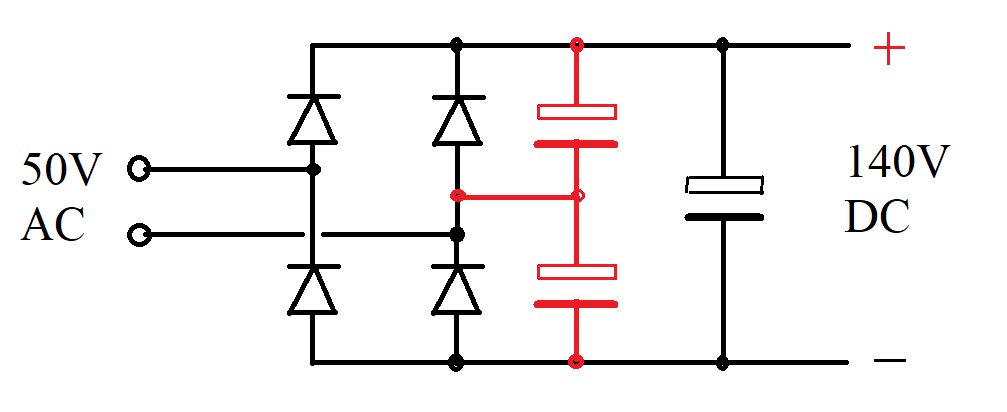 |
||||
Grogster Admin Group Joined: 31/12/2012 Location: New ZealandPosts: 9306 |
I looked up the DC-DC link, and now AE is locked into Dutch language, no matter what I do. Even if I log out, and back in again, it is still in Dutch.  Anyone know how to fix that? Smoke makes things work. When the smoke gets out, it stops! |
||||
Grogster Admin Group Joined: 31/12/2012 Location: New ZealandPosts: 9306 |
Ignore - found out how to change it back, but THAT was annoying - that AE assumed that cos I opened a link that happened to use Dutch, that Dutch was what I then wanted ALL of the ENTIRE of AE to then be in.....  Smoke makes things work. When the smoke gets out, it stops! |
||||