
|

|
Forum Index : Electronics : Variable input voltage bat charger
| Author | Message | ||||
| sPuDd Senior Member Joined: 10/07/2007 Location: AustraliaPosts: 251 |
Those Powernet units look quite impressive. The company has obviously listened to its customers. 55-264VAC input is quite a wide range. I'll have to experiment with a variac and see how far I can get one of my PSU’s to range. I made a UC3843 based SMPSU for +12V & +5Vdc operation. Its a version 1.0 unit, until I'm happy with it. Below is "FrankinSwitcher": 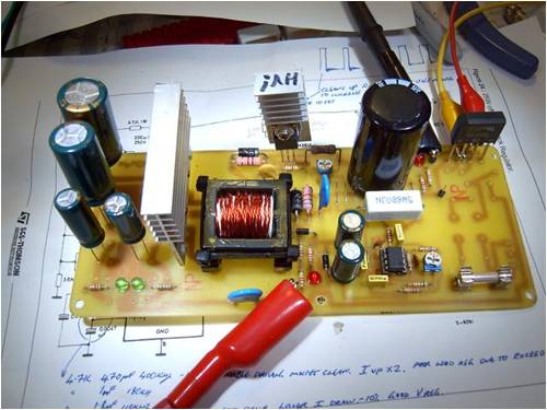
This is a generic 350W ATX PSU I re-wound for 48Vdc output. Worked, but needed better current control: 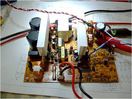
sPuDd.. It should work ...in theory |
||||
oztules Guru Joined: 26/07/2007 Location: AustraliaPosts: 1686 |
Looks like a 494 unit. the oztules current control will work on that I suspect. a few components and you will know. It'll make it very useful I should think. ........oztules Village idiot...or... just another hack out of his depth |
||||
| Dinges Senior Member Joined: 04/01/2008 Location: AlbaniaPosts: 510 |
Way cool, Spudd! Memo to self: convert a PC PSU to work from 2.5-55V.... Peter. |
||||
| vasi Guru Joined: 23/03/2007 Location: RomaniaPosts: 1697 |
The schematic or procedures will be available? Hobbit name: Togo Toadfoot of Frogmorton Elvish name: Mablung Miriel Beyound Arduino Lang |
||||
| sPuDd Senior Member Joined: 10/07/2007 Location: AustraliaPosts: 251 |
Oztules, yeah it was a TL494 system. I have a carton of Yaha units. I've played with the 494 since the mid 90's when we learnt SMPS in tech. Simple enough creature, but at the time I played with the ATX, I just wanted to see if it was possible. Scrapped it once I proved it would make 48Vdc. On a side note, when I get time I'd like to map out the circuit for the aux +5 & +12V system that runs all the time. I'd like to make some pcb's and move the transformer (and useful bits) over to it. Would make a handy PICAXE PSU for various projects. Then again, I might go Oztules on its a$$ and cut the whole circuit out of the ATX pcb with a 9inch angle grinder 
sPuDd.. It should work ...in theory |
||||
oztules Guru Joined: 26/07/2007 Location: AustraliaPosts: 1686 |
Spud, may I recommend the chainsaw for this??? 
The circuit Dinges pointed to will give you a fair idea of a generic type. The ones I have bothered to take notice of use 2 transistors to create the free running oscillator.. but makes no material difference. Dinges, as promised, I put a full wave rectifier on one of the ATX conversions. It puts out 44v@15A (very short time... just to get an idea... transformer will be the weak link first heat wise) I used 4x d92 which gives the rectifier about 40A 200v. I might replace the little switches with some bigger types and push it a big harder.... see what explosions I can get going. 
The current limit works perfectly on it as well. It will require a rewind to get any more out of it voltage wise... which is simple, and I would use a bigger core, and I suspect 500w would present no problems at all. As it is it will do as a soft/float charge for a 36v battery bank (car) if the wind don't blow. So the circuit as such seems to be quite stable. I may wind a bigger transformer... use bigger transistors, and see if we can get up to 1kw..... aiming for 108v@10A, and one at 56v@20A..... Heavy switching currents may introduce too much instability.... but it costs nothing to find out. ............oztules I've got a few 15A 900v fets.... maybe use the doubler with 400v caps... and ... and... Edit Sorry Dinges that should read 46v@15A Village idiot...or... just another hack out of his depth |
||||
| sPuDd Senior Member Joined: 10/07/2007 Location: AustraliaPosts: 251 |
Couldn't help myself: Marked out the PCB for angle grinder violence. Interesting to note the aux system uses about 25% of the board space: 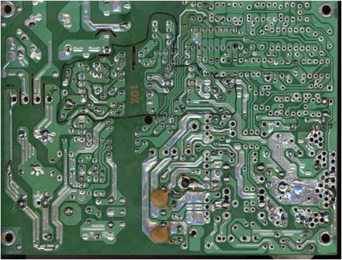
PCB with 150ohm resistor on 5V rail & some LEDs for load. Once cut out, I used the bench grinder to clean up the edges: 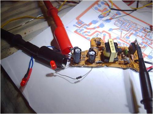
Making 5.1V and about 18V on the other rail: 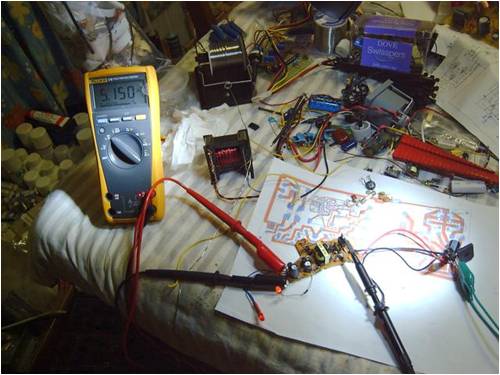
Waveform running at ~350Khz: 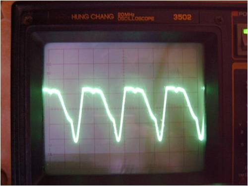
Transistor gets mildly warm, I suspect this is because it's almost a sine wave, as compared to if it were running from a PWM IC. I ran it on 40Vdc first to make sure it was OK, but it would randomly not turn on, or only output a few volts. Thought it was the opto coupler, turned out it is truly tuned for 340Vdc supply. Once on mains, it ran quite nice. Its not exactly efficient, but it works and could be useful on wind gens for powering monitoring gear or something. I suspect that the little transformer would work well if I drove it with a UC3842 or such PWM IC. Fun never the less. PS: The 9inch catfish is enough of a handful - chainsaw only good for spectators. sPuDd.. It should work ...in theory |
||||
| Dinges Senior Member Joined: 04/01/2008 Location: AlbaniaPosts: 510 |
Peter avoids eye-contact, makes no sudden moves and *slowly* walks backwards... The things one learns on this forum - from the various uses of a chainsaw (none of which involve cutting trees), to the angle grinder and the heatgun. No self-respecting electronics lab should be without those! Oztules, didn't expect full-wave rectification to have so much effect; so no need for rewinding the transformer then, apparently. (as long as you can live with 2.5-44V). Very interesting information. Rip out the old rectifiers, insert a (fast) full-wave bridge rectifier of adequate rating and be done with it? Up to 44V with hardly any work. Oh, and new electrolytic caps, of course. [quote=Vasi]The schematic or procedures will be available?[/quote] Vasi, I doubt a schematic would be useful in this case, as hardly any two PC PSU are identical (though they usually are very similar). If you read the stories on FL & this forum on converting PC PSUs, you will find there all the info you need. I recall someone (here or FL?) even describing how to rewind the transformer. Also, don't hold your breath for me to do this; last time it took 2-3 years of Oztules' whining for me to get my laze bones in action and modify a PSU; and at the moment I have to be content reading about the antics of others on this forum. But a girl can dream, can't she? Peter. (wonders if there is anything a chainsaw is *not* useful for in these guys' opinions... must be something in the water there) |
||||
oztules Guru Joined: 26/07/2007 Location: AustraliaPosts: 1686 |
Spud!!! A 9inch angle grinder on a little circuit board 
I bow to your destructive prowess. I know when I'm beat. Perhaps change beaker to animal 
I just came in from playing with the full wave rectified unit. The waveform on the output is a perfectly clean square waveform... eventually... it wasn't always so. .........oztules Village idiot...or... just another hack out of his depth |
||||
| sPuDd Senior Member Joined: 10/07/2007 Location: AustraliaPosts: 251 |
I'm wondering now if it would make sense to design a decent 12, 24 or 48V PSU based on the ATX design with the intention of using old/new ATX units as major parts donors. The difficult to build transformers are already built and tested. The ATX case is an ideal size, fan already fitted, aux 5V & 12V rails while asleep, wide input range etc etc. A new PCB would be nice, more reliable solder joints, better layout, better filtering, auto input voltage switching, maybe even temp compensation and external voltage adjust... Got to be cheaper than the $500-$800 places want for a 10A 48V PSU. On a side note, I dismantled the main transformer in a genuine 550W ATX I had for a long time. I found both ends of the primary winding ended inside the transformer with an almost full wrap of copper strip. The primary measured O/C. The unit was working, just leaking caps. I'm assuming it was used like the pulse cap in series in most ATX units, but it already had one of them as well... odd. sPuDd.. It should work ...in theory |
||||
oztules Guru Joined: 26/07/2007 Location: AustraliaPosts: 1686 |
Sorry Spud, That full strip/s is a shield "winding". Some have one some have two .....some have none....what noise??? It is to suppress noise, and is connected to where ever the hell they please. Some with 2 shields connect both to one of the primary inputs, with each wrapped in the opposite direction to the other, others I have seen connect 1 to each of the secondaries.. the outer to the opposite input and the inner to the other input.... sometimes to the same input. You should of had to chew through the outer primary half to get to the first shield. The second shield should have been before you peeled of the last primary half (the last wires on the bobbin). Yours sounds like one to each input. There will have to have been 2 windings there of probably about 19T on the outer most, and inner most windings. They will connect as a centertap (blanked off from the world... usually between the two input pins but cut off short). If during dismantling, you disconnect this CT, it will show open circuit... maybe thats where the confusion came from. Pulsed DC needs to have a material path to travel... capacitive coupling wont do. The capacitor that supplies the DC power to the primary is ok however, as it is pulsed in both +- and then -+ depending on which switch is closed.... 1/2 mains potential each/ opposite way.... Hope that clears it up. ..........oztules Village idiot...or... just another hack out of his depth |
||||
| sPuDd Senior Member Joined: 10/07/2007 Location: AustraliaPosts: 251 |
Oztules, I suspect you may be right, I even drew pictures and took notes as I dismantled it, but perhaps I missed the centre tap. Has me wondering now. I agree that a continuous winding is required for it to work, but there is some sneaky designers out there that have never wielded a revving chainsaw while laughing like a maniac, let alone seen sunlight.... you never know what these disturbed individuals will come up with next 
I tell you what though, these ATX PSUs are quite the victim of our modding madness. Can we be topped? Can we be stopped!? I hope not sports fans! Tune in tomorrow, as we turn an ATX PSU into a satellite, and magnetically launch it into orbit! sPuDd.. It should work ...in theory |
||||
| Dinges Senior Member Joined: 04/01/2008 Location: AlbaniaPosts: 510 |
Oztules, Your full-wave bridge rectifier modification had me wondering for a while; didn't see how it'd nearly double output voltage (from about 24V to about 46V). Till I realized: the transformer is centertapped! Doh! Normal operation is like this: 
which you modified to this, I think? 
So, basically ignore the centertap (leave disconnected) and connect the bridge rectifier diodes to the two end-connections of the transformer? Probably is trivially simple for you, but I've been thinking about this for a few days trying to figure out how it could work. Till the centertap thing hit me. Feel like an idiot for not thinking of that earlier. In that case, we shouldn't expect to get the same amount of current out of the transformer, as the wiresize is no longer adequate. Besides, doubling voltage at the same current would lead to doubling power... probably leading to an unhappy little transformer. Also, for current-control to work in that case, you wouldn't be using the old flying-lead wire with a bit of wire inserted to lift 'ground' up a few mV, but you'd insert the wire between the negative terminal of the bridge rectifier and the rest of the circuit? Same principle though. 15A at 46V... I hope you wear safety glasses and earplugs when playing with it. 
Peter. (lustfully eyeing the single ATX supply left...) |
||||
oztules Guru Joined: 26/07/2007 Location: AustraliaPosts: 1686 |
Dinges, Your assessment is basically correct. Current control is on the negative to earth (centertap lifted out of the board and terminated). Same piece of wire loop and same circuit. The output windings see the same currents as before, but the duty cycle is doubled. Being only 4turns and 2 1/2 turns, of pretty thick wire, there will be little extra heat from here. The primary will be expected to do twice as much as before though, and it is 19Tx2... so I would expect that to heat up considerably if you double the output for any period of time. Saturation is the main problem I suspect. The transistors will need better heat sinks than some I have seen, but generally, the ATX have better cooling fins than some of the flat excuses I have seen in the AT. The transformer in this particular ATX is pretty robust, with .8mmX2 and X5 for the 11 turns... a lot of copper... very small resistance. The primary though is only .8mm for38 turns... still only 3 or 4 feet of wire... but this will have to carry an average 3A or so if we want 400W out of it. So the figures are not that daunting. I have used this one for a 10A 24v charger (28v), and it does it without complaint. A simple solution is to either double up the transformer count (if you have 2 the same you could piggyback them), or just use a larger core and rewind... simple stuff. I built a 36v charger years ago using this topology, and for a E35 core it was no problem. The switchers in some supplies are the larger types and I have driven these to over 600w for extended periods. Perhaps if you and Spud want, we can make a generic supply that will be easy to build from scratch with ATX parts. It's a funny world. Much is made of design of the circuit board because of critical placement of tracks and components. In the real world, I have a 1.5 and 2.5kw unit, where the switchers are about a foot from the transformers, the current transformer is about 8" away, and the rectifiers are about the same. It has virtually no input filter caps (8uf only) and is air cooled ... no fan..... so all rules are there to be broken (picture in my anotherpower files pics here ).... probably the best charging unit I have ever seen. Will probably never fail as there are no electrolytic in sight. From what Spud says, there may be a project in the making here somewhere. .............oztules Village idiot...or... just another hack out of his depth |
||||
| sPuDd Senior Member Joined: 10/07/2007 Location: AustraliaPosts: 251 |
Dinges, pop into your local computer repair store and ask if you can have their junk computer gear. You may get suspect looks, just tell them your using it to make artwork (explaining chainsaws, heat guns and grinders to them is likely to scare the little darlings - don't do it!) From mobo's you get a big CPU heatsink with fans, all sorts of useful connectors, etc. Hard drives are full of useful bits, ATX PSU’s are no brainer etc etc. Once they get to know you, you'll find they'll even keep selected goodies for you to pick up 
Oztules, I do like the idea of a generic PSU from donor ATX units. Do you think we can get carbon credits for it? 
I'd say keep the PCB outline to the ATX standard footprint, so it goes right back into the case. Perhaps safety rate them at ~250W each, and they can be stacked for modular battery bank charging. I'll do a bunch of measurements and survey the range of variation within the ATX family parts. sPuDd.. It should work ...in theory |
||||
| Dinges Senior Member Joined: 04/01/2008 Location: AlbaniaPosts: 510 |
Oztules, that'd be one project I'd follow with interest, though a full-bridge modification will likely be the first next thing that I'll do to one of those PSUs. 2.5-46V @ 5A is actually VERY nice and probably more than enough for me. Quick & easy modification. But there are some grapefruit-sized ferrite transformer cores lying about here that are waiting to be put to good use. Been saving them for years, not really knowing why. Thought they might be useful for something, sometime... Maybe sometime arrives quicker than expected. Spudd: I planted 3 apple trees last year; I'm willing to give you the carbon-credits for it (as long as I get to keep the apples!) Peter. |
||||
| Bolty Regular Member Joined: 03/04/2008 Location: AustraliaPosts: 81 |
Hi guys. I have only just found this post. My excuse is that I normally only check the Windmills section and I have been holidaying a lot lately! Very interesting reading and great work by all of you! I have played around with many SMPS going back to the 1960's where they only used discrete components and were very rudimentary. These were particularly valuable for high voltage outputs, for use with valves in portable equipment in those days. Since the mid 90's I have had some "fun" repairing school computer power supplies. These were in Burroughs computers. It was necessary for me to repair these at that stage, as our school had no financial resources to purchase IBM PC computers.Since then I have adapted PC power supplies for various purposes. As mentioned earlier, many PC power supplies utilized 494 control IC's. Many other supplies that I have acquired utilized strangely marked IC's like 2002, 2003 etc. Do any of you guys know what these chips are? Are they rebadged 494's? Do you have any idea why they are labelled such as this? |
||||
| sPuDd Senior Member Joined: 10/07/2007 Location: AustraliaPosts: 251 |
It seems to me that the original ATX circuit and the diagrams I've seen all use the dead-time control input to adjust the output. Is this correct? I've tried using the error amps but below 100% duty cycle it squeals and carry’s on like a pork chop. Only seems happy at 100% duty cycle. If I increase the DTC soft start cap to say 100uF, I can see it slowly starting on the CRO without any complaints. Output voltage rises slowly and duty cycle increases slowly as well. Is this due to the push-pull layout? Anybody else got this problem? Doesn’t seem right to me. sPuDd.. It should work ...in theory |
||||
oztules Guru Joined: 26/07/2007 Location: AustraliaPosts: 1686 |
The dead time control is normally used to kill off the chip in emergencies (over volt, over current) or the put it to sleep, soft start and wake up functions. It can be used as a control for fixed pulse width ratio work as well (If you have read Flux's matching the load, this would be a way to control the current system for a boost control... 50% for doubling and wind back as current goes up.) The pork chop behavior is due to instability in the error amp input circuits. If you are using only one op amp (as normal) try a 1uf (or even 2uf)capacitor across the pin2 to ground. If using the current control loop (like Dinges and me) then another cap across pin15 to ground will help. The response time will suffer a bit, but is of no real importance. But it should stop the harmonics, and clean the wave up. It should be a good square wave. If not, you just know you are feeding some rubbish into the error amps from somewhere.. , or you have the gain too high. Pin 3 is your feedback point for both error amps. In the last few conversions, I just ground pin 4 and be done with it.... one less thing to play with 
If it squeaks and squeals, you have input instability problems (pin 2 and / or 15 if used). The pulse train is dependent on the output of the error amps. Any noise going into them will create havoc. The push pull topology plays no part in the development of clean pulses. If you get excessive ringing that you cant damp in the output, this will present to the input and cause noise too..... hence the big caps I suggested. The damping should already be in place in this instance... as they have done it for you already. With the big soft start you introduced, and with the error amp/s pushed full bore, you had no noise problem. The error amps were turned full off (max pulse width)... so could not be swayed with noise, and the soft start signal (100uf with controlled V going down to zero also could not introduce noise. Thats why it seemed so stable.... it had no choice. You could control it with pin4, but when you introduce feedback from the output to pin4. to control the output voltage or current.. the same noise will stop you again... Get the noise out of the error amps and all will be well. ..............oztules Village idiot...or... just another hack out of his depth |
||||
| Dinges Senior Member Joined: 04/01/2008 Location: AlbaniaPosts: 510 |
I've had the same issue of screaming/squeeling of the modified PSU too. Frequency varied but was about 1.5-2 kHz, and could be varied by varying output voltage and loading. It was present in my first PSU conversion, even before implementing the current-control: " Adjusting voltage from 2.5 to 15 V worked perfectly, but below 9.5 V the PSU starts audibly whining; the frequency of it goes down as voltage goes down." http://www.fieldlines.com/story/2007/10/18/16953/116 Funny thing was... the loads I was using, H4 car headlight bulbs (12V/60W) worked as speakers, with their coils vibrating at the 1.5-2kHz frequency. Noise became mechanically amplified when the glass envelope of the lamps touched a board or box. I just remember: with that first PSU I tackled, it would start to oscillate too just by the act of touching pin 1 and/or 2 of the TL494 with the DMM probes (to measure voltage at those pins). Removing the DMM probes didn't stop oscillation once it had started. Never bothered to have a closer look with the scope. Oscillations were not an issue in all of the PSU conversions, but more than one suffered from it. Next time it occurs I will give the the 1u/50V capacitors a try too. One thing I also add nowadays is a decoupling capacitor (100n-220n) from the wiper of the voltage adjustment potentiometer to ground. It stopped the overvoltage protection from kicking in when adjusting the output voltage (from noise of the potmeter) in one particular case, and ever since I'm adding it. So far, the PC PSU in the capacitor-discharge spotwelder has withstood a lot of rough use; from complete shortcircuits (every time a weld is made) to recharging an empty 1.5F/25V capacitor bank at 10A, and that repeated many times over. I'm guessing about 1000 weld cycles so far, with 2 shorts per cycle. Peter. |
||||