|

|
Forum Index : Microcontroller and PC projects : Colour Maximite 1.5? or something
| Author | Message | ||||
| Mixtel90 Guru Joined: 05/10/2019 Location: United KingdomPosts: 6787 |
OOH! Things are happening. :) Mick Zilog Inside! nascom.info for Nascom & Gemini Preliminary MMBasic docs & my PCB designs |
||||
| matherp Guru Joined: 11/12/2012 Location: United KingdomPosts: 9115 |
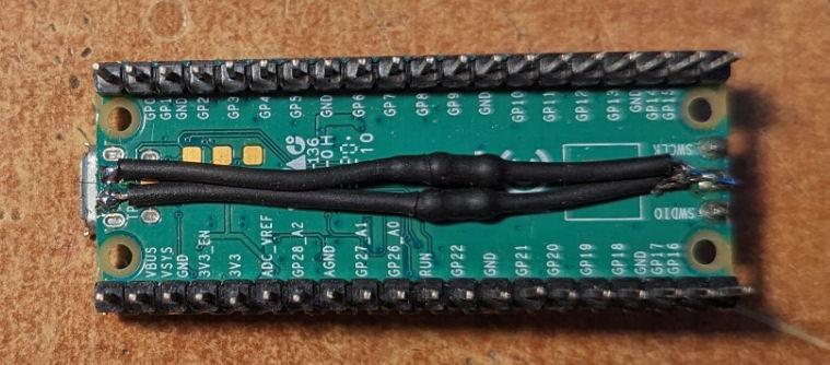
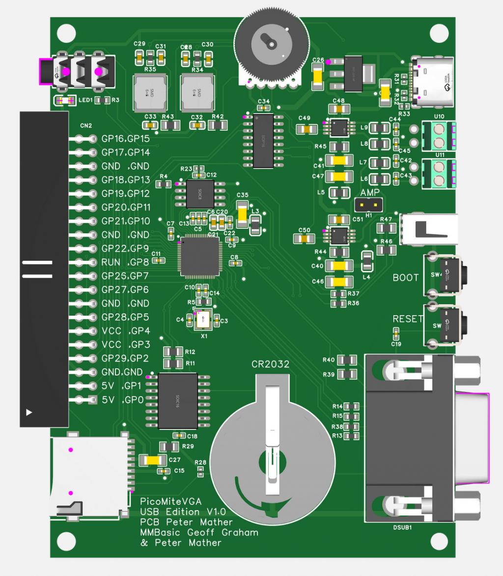
Request for BigMik With your hubs that don't work with the Pico, please could you try the following: Add a 15K resistor from TP2 and TP3 on the bottom of the Pico to GND  This is part of the spec of a USB host. I was having the issue that enumeration failed after a reset of the Pico but worked after a power-up. Adding the resistors solved the issue Here is the final version of the PCB which is now in production Changes are: Different audio jack - apparently the original didn't have the temperature rating for their soldering process Different CR2032 saocket to better clear the DS3231 chip 15K pulldown resistors added to the USB host port Heartbeat led re-located to the "front"  Edited 2024-01-30 18:05 by matherp |
||||
| Frank N. Furter Guru Joined: 28/05/2012 Location: GermanyPosts: 828 |
That is very interesting! That could also explain my problems with the HID2CDC! I really must try this out! Thank you Peter! ...would it be possible to introduce this USB functionality to the standard PicoMite??? It would be great to build a small independent device with an SSD1963 display as a terminal and a small wireless keyboard like this one:  Frank P.S.: Unfortunately my HID2CDC still does not work despite resistors...  Edited 2024-01-30 20:37 by Frank N. Furter |
||||
| Mixtel90 Guru Joined: 05/10/2019 Location: United KingdomPosts: 6787 |
It is more or less a standard PicoMite really. GP8 and GP9 become the console connection via a USB-TTL converter and the normal RP2040 USB connection, normally used for the console, becomes the USB host port. The firmware has been changed, obviously. Mick Zilog Inside! nascom.info for Nascom & Gemini Preliminary MMBasic docs & my PCB designs |
||||
| Frank N. Furter Guru Joined: 28/05/2012 Location: GermanyPosts: 828 |
Can an ILI9341 or SSD1963 then be used as a console? That would be a great enrichment! Frank |
||||
| Mixtel90 Guru Joined: 05/10/2019 Location: United KingdomPosts: 6787 |
Not at the moment, but I suspect the USB code will be put onto the standard PicoMite as well as the PicoMite VGA. The LCD display would be just that - the display. The USB system is replacing the original PS2 keyboard. Mick Zilog Inside! nascom.info for Nascom & Gemini Preliminary MMBasic docs & my PCB designs |
||||
| robert.rozee Guru Joined: 31/12/2012 Location: New ZealandPosts: 2350 |
far more than that. as a USB HOST the picomite VGA will be able to accommodate keyboard, mouse, sony PS3 and PS4 games controllers, CDC serial ports, etc. hence why Peter has used the term "Colour Maximite 1.5". there is also the possibility of USB attached display devices. ie, a secondary pico with an LCD screen attached that acts as the console display. the USB connection can supposedly handle data rates up to 12Mbps, surpassing(?) that supported by the pico's SPI controller. btw - Peter, you appear to be permanently dedicating two pins to a serial console. this isn't really necessary, as a serial console port can be created by just plugging a USB-to-serial adapter in place of the USB keyboard. cheers, rob :-) |
||||
| JanVolk Senior Member Joined: 28/01/2023 Location: NetherlandsPosts: 144 |
Peter Looks good. Some more points for improvement. The option list is still missing from the PCB. The coding is not yet available for all components, as is the case for all ICs and various components. Place some more information such as L, R, GND and other connectors at U10 and U11 or the soldering location. For the 40 pin main connector, is it possible that 3V3 is better than VCC? I see that the Vref power supply also has better interference suppression through L3 and why is this not present on the main connector? A possibility would be to replace VCC -> Vref and a GND pair with a 3V3 pair, leaving 3x 3V3 pins and a Vref and the layout remains fairly standard and no longer a shortage of 3V3 pins? Jan |
||||
| Volhout Guru Joined: 05/03/2018 Location: NetherlandsPosts: 4233 |
Next revision maybe..... PicomiteVGA PETSCII ROBOTS |
||||
| Volhout Guru Joined: 05/03/2018 Location: NetherlandsPosts: 4233 |
@Peter, About the boards, what do I need to provide myself ? The 40 pin I assume ? All other TH parts ? Potmeter/VGA/vertical USB/ screw terminals ? Volhout PicomiteVGA PETSCII ROBOTS |
||||
| Mixtel90 Guru Joined: 05/10/2019 Location: United KingdomPosts: 6787 |
If there is trouble with the USB stack for some reason the Pico's only USB port, and hence anything connected to it, is disabled. I suspect that's why a console via GP8/GP9 was considered desirable. The only way out of a mess like that otherwise is to reload MMBasic and possibly lose everything in flash. Only guessing. Mick Zilog Inside! nascom.info for Nascom & Gemini Preliminary MMBasic docs & my PCB designs |
||||
| matherp Guru Joined: 11/12/2012 Location: United KingdomPosts: 9115 |
Nothing except a battery, they come ready to run |
||||
| matherp Guru Joined: 11/12/2012 Location: United KingdomPosts: 9115 |
Another update I bought the cheapest USB gamepad on Amazon UK and it is working perfectly over USB on the CMM1.5 |
||||
| Mixtel90 Guru Joined: 05/10/2019 Location: United KingdomPosts: 6787 |
Excellent! I got two of those from AE for roughly half that price. One didn't work on arrival - it needed me to fiddle with it before it did (broken track at one of the button pads). They both work fine under Windows now. I bought them to see if they were suitable for conversion from USB to SNES or I2C. No need to continue with that now. :) Mick Zilog Inside! nascom.info for Nascom & Gemini Preliminary MMBasic docs & my PCB designs |
||||
| JanVolk Senior Member Joined: 28/01/2023 Location: NetherlandsPosts: 144 |
I also have this game pad. Then it will soon be universal and plug a USB keyboard into the USB slot of the PicoMiteVGA 1.5 to write and adjust a program and you are done, then insert the USB game pad into the USB slot and start gaming. I'm looking forward to the latest firmware version to try it out. Jan |
||||
| matherp Guru Joined: 11/12/2012 Location: United KingdomPosts: 9115 |
I need some inspiration - Tom where are you? The firmware will support a 4-port hub so up to 4 gamepads + a Wii Classic in a worst (best?) case. I will modify the DEV WII function to be DEV(GAMEPAD n,function) where n is 0 (Wii classic) to 4 (1-4 represent the 4 slots on the USB hub). This is basically the same as the CMM2 approach. The issue is that I can't see an automated way for the Basic program to know which channel is connected to which USB controller. AFAIK TinyUSB doesn't give any information on which port on a hub a device is plugged into. For convenience in the firmware I would like the channel to be just the order in which USB devices are enumerated. So if I plug in a keyboard and then a controller. The controller would be on channel 2 so DEV(GAMEPAD 2,B) would return the state of all the buttons as per the Wii Classic. I can easily add a MM.INFO function MM.INFO(USB n) which returns what is on which channel KBD, MOUSE, PS4, PS3, Generic or MM.INFO(GAMEPAD n) which returns the channel of the nth Gamepad but you still can't distinguish between two connected generic gamepads. Maybe, this is something the Basic program has to do? "Player 1, Please press your Select button" MM.INFO(SELECT PRESSED) ' returns 1 to 4 if USB Thoughts |
||||
| thwill Guru Joined: 16/09/2019 Location: United KingdomPosts: 4039 |
I didn't realise I was your muse Peter, I'm not sure I can handle that sort of responsibility  . .Definitely. 1. Press START to play 2. Poll USB/Gamepads 3. First one to read START is player 1 4. And if necessary second one to press START is player 2, etc. There is no imposition by the firmware of channel 1 <=> player 1, channel 2 <=> player 2. Don't add any special function to read START/SELECT. Ensure DEV(GAMEPAD n, function) returns something useful (not an ERROR) if n is not a gamepad. Best wishes, Tom. Game*Mite, CMM2 Welcome Tape, Creaky old text adventures |
||||
vegipete Guru Joined: 29/01/2013 Location: CanadaPosts: 1109 |
Can you specify more closely yet what n actually means? The Wii Classic is connected to (one of the) I2C channels. Is it out of the question to connect 2 Wii Classics, each on a different I2C channel? Then n would refer to I2C channel. Then the USB controllers could be numbered with, say, negative addresses. Visit Vegipete's *Mite Library for cool programs. |
||||
Grogster Admin Group Joined: 31/12/2012 Location: New ZealandPosts: 9306 |
Grogster might.  In fact, I will. I'm watching the thread with interest, but as soon as Peter and the other testers have tested the prototypes and are happy with things, I will certainly add them as a product on my website. Fully assembled/programmed/tested board only. No case at this stage. Smoke makes things work. When the smoke gets out, it stops! |
||||
Grogster Admin Group Joined: 31/12/2012 Location: New ZealandPosts: 9306 |
Oh, and on the CR1220 button cells - over here in NZ, they are dead-easy to find, and not expensive. I expect that is a situation that Peter is also familiar with, where-ever he is in the UK. I HAVE had plenty of people - mostly from America - who have bought CMM2's who say that the 1220 cell is very hard to find, and they have to go to specialist jeweler shops to get one, and the mark-up makes them fantastically expensive purchased that way. As batteries like this are a prohibited item, I cannot ship the CMM2's anywhere with the button cell included. Technically I COULD, but if customs did a check and found a cell in there, I would be the one who would get in trouble for it, so...... Having said that, the move to the 2032 cell is a good move. Those cells are easy to get anywhere as far as I know. It was only via CMM2 sales, that I even was made aware that the 1220 cell is hard and expensive to find in some countries. Live and learn.  Smoke makes things work. When the smoke gets out, it stops! |
||||