
|

|
Forum Index : Electronics : Various aspects of home brew inverters
| Author | Message | ||||
| nickskethisniks Guru Joined: 17/10/2017 Location: BelgiumPosts: 458 |
Brilliant! Poida, something to investigate is the electrical resistance between de mosfets and the heatsink used as a main conductor and how to improve it. When I was trying to make a pwm regulator for my solar array, wich I failed... I discovered a high transition resistance between the mosfets and heatsink. I was using the IRFP4110 mosfets, 8 in parallel gave me about 1mOhm resistance. This should have gave me 0,46mOhm! |
||||
| Solar Mike Guru Joined: 08/02/2015 Location: New ZealandPosts: 1138 |
Raw metal alloy heats inks have a thin oxide coating due to the metal reacting with the air, just prior to attaching your mosfets get some 1000 grit emery sandpaper moistened with kerosene and shine up the areas where they will attach. Wipe clean with a rag and solvent and smear a very thin coating of white petroleum jelly over the surface, then after wiping the backs of the mosfets bolt together. Don't use any form of heat sink gunk in this instance as it prevents making a good electrical contact. Some mosfets are not very flat across the back tab, this will prevent good connection and have poor heat transfer, you can lightly grind them flat with emery paper and a flat surface (sheet glass) Cheers Mike |
||||
| ltopower Regular Member Joined: 08/03/2019 Location: United KingdomPosts: 64 |
Been having a look over the results of the tests I did in relation to the input ferrites and something does not seem right... The ferrites are all E70/33/32 and I tried between 2.5 turns and 8 turns for 1, 2 and 4 ferrites in parallel. The 4 ferrites were accross the 4 separate windings and the 2 were paralleled with 2 windings. What seems odd is that I have a lower standby current with twin ferrites (3 turns each 87uH ungapped, 9700AL) at 43.5uH than a single ferrite with 4 turns at 155uH ? This is at idle, no load at all.. had a look on the scope and the leading and trailing edge of the PWM have some small >10MHz ripple for about 5 cycles on the switch off. 4 cores at 4 turns each (115uH) so 38.8uH gives a lower standby than 1 core with 6 turns at 349uH.... So, this is making me think that it is not the inductance that actually counts as much as the basic volume for ripple reduction. But at Idle I would not have thought the ripple would have as much of an impact. The differences are small though at less than 1W or sub 5%. Does any of that make sense ? |
||||
| tinyt Guru Joined: 12/11/2017 Location: United StatesPosts: 438 |
In addition, for good electrical contact between parts that are exposed to thermal expansion/contraction, I think using spring washers on the screws/bolts will help maintain the needed pressure between the faying surfaces. |
||||
| ltopower Regular Member Joined: 08/03/2019 Location: United KingdomPosts: 64 |
Also thought of a way how to avoid the use of non ferrite spacers... and have an accurate spacer.. Ribbon cable ferrites offer a large flat area and these can be cut at each end and then used as 2 spacers for the outside 2 legs od an E core, glued in place to stop the buzz... The ribbon ferrites ar around £1 each and one can make 2 spacers.. This gives the benefit of adding in extra winding window space because the gapped material is no longer non-ferrite... These should gap an E70 if my thinking is right... https://www.mouser.co.uk/ProductDetail/875-28R1496-000 Will likely be ordering some to see how well they work out.. |
||||
| ltopower Regular Member Joined: 08/03/2019 Location: United KingdomPosts: 64 |
Been going back over the previous tests to try and piece together the 2 characteristics the primary inductor offers up.. Poida Part 7 - page 8 - I think you have a mistake on the ferrite as you are indicating 2 turns and 50uH, which is not possible. There is a particular reason why this matters... Part 17 - page 13 - The powerjack choke just needed 1 extra turn applying to give 63uH... the 2 turns 28uH was just below that needed to delay the gate switching. My chart of uH vs Idle with the knee point around 20-30uH.. The tests on part 7 were particularly interesting in relation to the ripple.... the reason I believe has to do with W = 0.5 x L x I^2 for the core and how the inductance decreases closer to saturation.... The idle ripple is to do with basic stored energy in the inductor, separate to the effect on the MOSFET gate switching resistance. These are two completely different effects... This would explain some of the reasons for the odd differences in ripple on the choke and the resulting impact on idle current draw. The 14uH steel would saturate far later and hence store far more Joules than the higher uH ferrite that saturated out earlier with a lot lower end uH.... The ferrite + steel offer up the : Ferrite : MOSFET switch on current blocking Steel : mJ stored energy for ripple reduction (physically smaller inductor) So, a combination is possibly optimal for this reason. block + stored joules. Steel on it's own does not block the high di/dt.... seen by high idle ripple (and blown FET's as per Part 15) BUT steel has higher saturation B to store way more energy... Ferrite on it's own can't store enough mJ for large inverters (unless really big..).... high load ripple. Now wondering if a small M2 grain orientated steel toroid core + Ferrite make the optimal balance... OR does the ripple after the primary inductor really matter at all and only the ferrite is actually needed ? Maybe I'm still catching up though.... or still getting 1+1 = 7 |
||||
| ltopower Regular Member Joined: 08/03/2019 Location: United KingdomPosts: 64 |
Trying to work out the numbers.... My transformer 6kVA 4 x 29V secondaries, 17 turns, 1.42T flux, would appear to store around 28 Joules per secondary or 112 Joules total (AL 2288 Ac 56.25cm3).. so adding a smaller 80uH core inline, to store an additional 1 Joule at the most, seems rather token... At a PWM switching of 23.4kHz and a 20% duty off cycle time for a load of 6000W at 48V the off time is the equivalent of 4.92 Joules. So, this is potentially where 1 Joule can make a difference.. E70 ferrite no airgap 5 milli Joules... E65 ferrite 0.5mm airgap - 24 milli Joules.... The Aerosharp even at 50A with 50uH only stores 125mJ, still way more than the E65.. E70 ferrites (4mm gap) - 234 milli Joules. 4 x E70 4mm gapped ferrites.... 1 Joule.. Think I just realised the 0.5xLi^2 link back to saturation, inductance and stored energy. The store is finite, once full as I increases L just decreases as required... for our inverters L is irrelevant after the initial few nS switching, it's just Joules after that, or ? 1 + 1 = 27 hurray ! |
||||
| ltopower Regular Member Joined: 08/03/2019 Location: United KingdomPosts: 64 |
Bit more testing... gapped two of the E70's with 6 sheets of paper so around 0.5mm to 0.6mm gap, which should bring the AL down to around 1500. Added 8 turns to each E70, so approximately 102uH (still waiting for the inductance tester to arrive.....) and then connected in parallel so overall approx 51.2uH... Idle current is now even lower than ALL of the previous test combinations, but there is something a little odd, or not ? 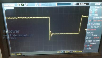 The switch off is showing some ringing and an overshoot..... the switch on shows nothing significant. Now, I do have the supply for this test setup rigged up to a boost converter, which is also showing ringing, which I'm now presuming is the inductance energy trying to go back to the source supply after switch off ? That's my guess and probably wrong... Quite puzzled how idle has dropped further with such a small gap added even though the E70's are nowhere near saturation currents. Does the very small air gap impact the di/dt that much ??? |
||||
| ltopower Regular Member Joined: 08/03/2019 Location: United KingdomPosts: 64 |
These are the E70's (twin wire as its one wire per winding, could have joined them and made it easier with a single wire...). 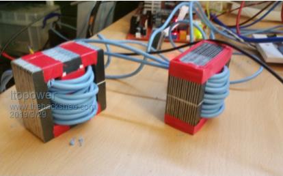 |
||||
| ltopower Regular Member Joined: 08/03/2019 Location: United KingdomPosts: 64 |
This is a better capture on the scope... my scope is not quite as good... 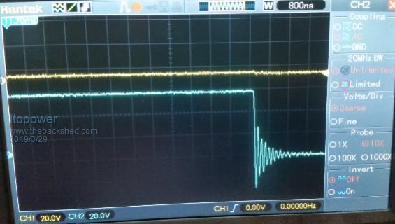 This is a switch off with the ringing. around 6.25MHz. |
||||
| ltopower Regular Member Joined: 08/03/2019 Location: United KingdomPosts: 64 |
Realised the gap was 0.5-0.6mm across so the gap the inductor sees is double that.... so re-wound with 12 turns (approc 126uH each) of single wire this time and the idle dropped even further to around 19W. The signal is now sort of clean.... Switch on as the top trace and the switch off on the bottom. 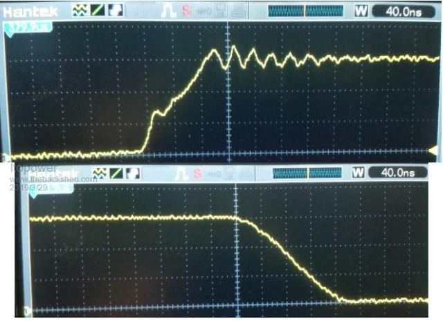 |
||||
| poida Guru Joined: 02/02/2017 Location: AustraliaPosts: 1420 |
Poida Part 7 - page 8 - I think you have a mistake on the ferrite as you are indicating 2 turns and 50uH, which is not possible. There is a particular reason why this matters... If it was a N87 type, 70 x 33 x 32mm, the AL is 9,700 2 turns inductance = turns2 x AL = 4 x 9.7 uH = 40 uH I might have had an extra 1/2 turn... Or it was the N27 material. This is near enough for government work. I was surprised when I measured it with the BK Precision 879B LCR meter. It might have been 49 or 50uH... The TDK specs show AL values +30%/-20% wronger than a phone book full of wrong phone numbers |
||||
| poida Guru Joined: 02/02/2017 Location: AustraliaPosts: 1420 |
My thoughts on the ringing are that it's due to the paralleled MOSFETS. One conducts just that little bit before the others, and then the whole thing is monstered by that eager switch, pulling the Vds down a lot, on it's own, then it lets it rise, the others might switch on then, pulling it down, Vgs now is altered, letting the switches open a bit, and so on. A right party with lots of booze. I am very keen on the idea of separate primaries for each of the full bridges. This will mitigate the Vds thing with parallel switches. But be extensible to the power needed. All with clean switching. My house still runs on an Ailexpress board (3 x 4 HY4008), into a 3kVA toriod, with an E70 ferrite choke -only-. I disable the over current gate drive shutdown. TVS 18V devices on the gates. September 2018 and counting. wronger than a phone book full of wrong phone numbers |
||||
| noneyabussiness Guru Joined: 31/07/2017 Location: AustraliaPosts: 513 |
I think they might be useful, what are the winding voltages? I am hoping convenient. I don't want to hand wind a 100V at 0.3V/turn. Ill check them out as soon as i can. I have 1 bare transformer, but the others are still factory set... Let me know if useful and which one/s you want... 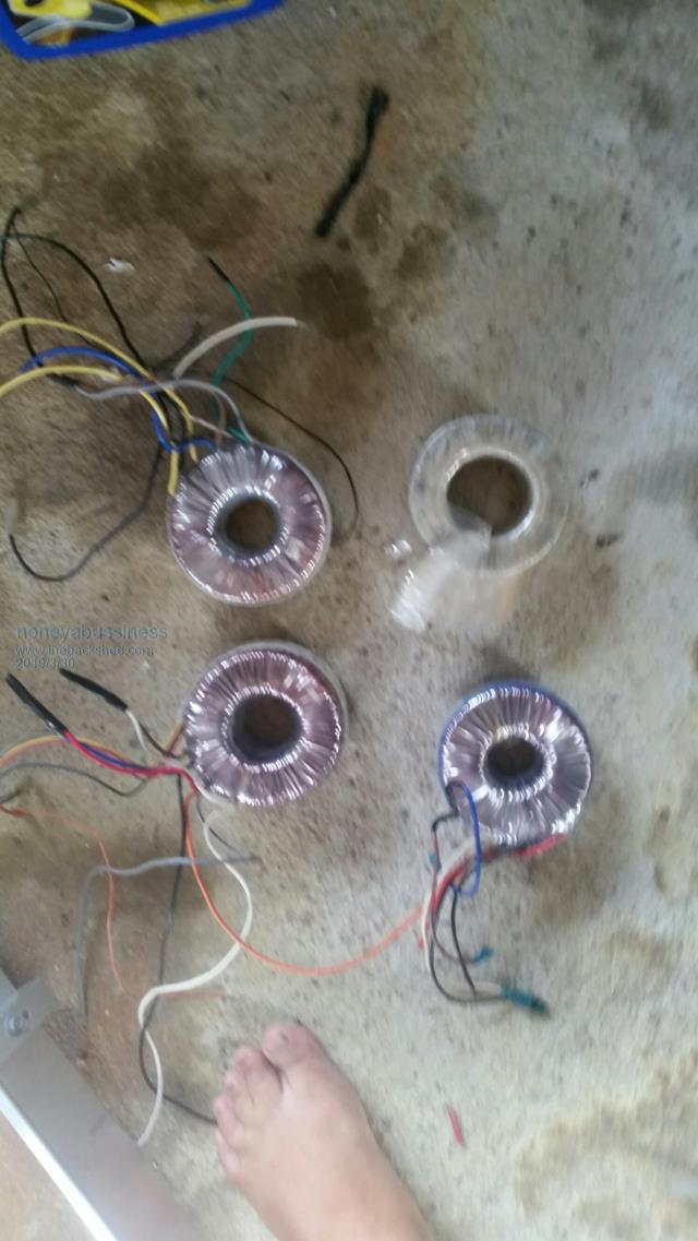 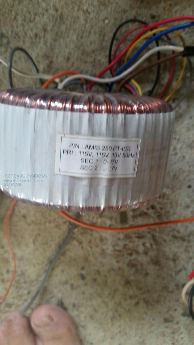 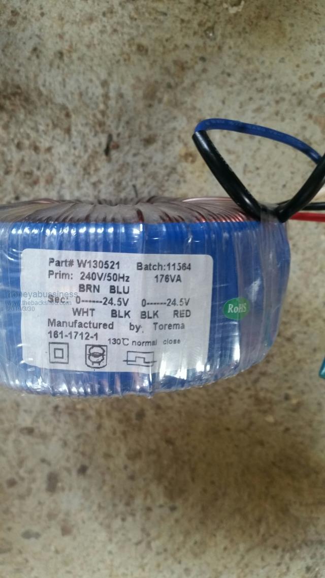 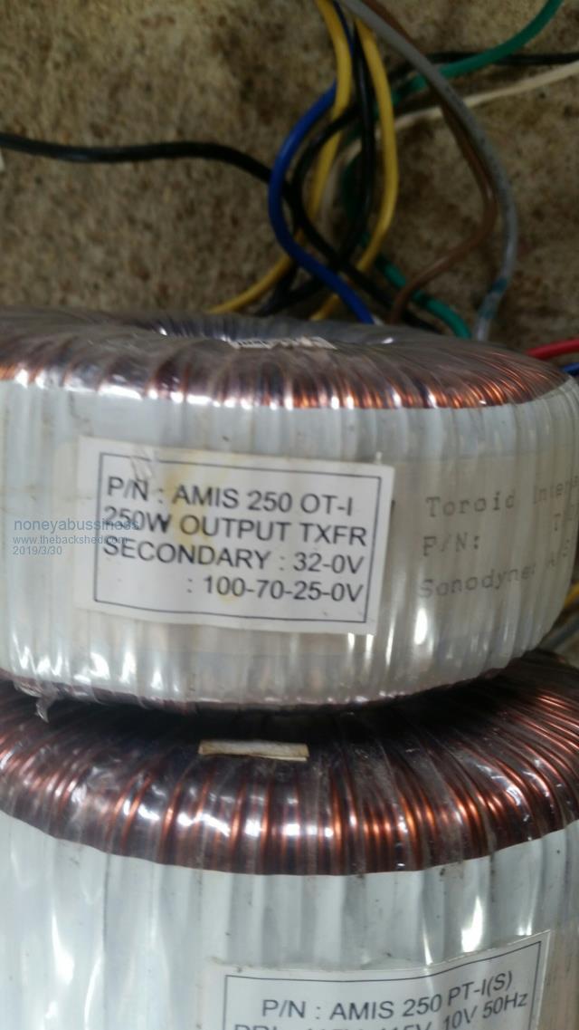 I think it works !! |
||||
| noneyabussiness Guru Joined: 31/07/2017 Location: AustraliaPosts: 513 |
The first primary voltage is 27v I think it works !! |
||||
| ltopower Regular Member Joined: 08/03/2019 Location: United KingdomPosts: 64 |
Two questions... First one is what does everyone do for output filtering ? EMI and or any other ? Second one is transformer resonance - Scenario is a transformer under say a 4kW resistive load (couple of electric heaters plugged in) with a 4.7uF capacitor attached to create a 75Hz resonance. The inductance from the 75Hz resonance with a 4.7uF capacitor is therefore around 950mH for the transformer. An extra 5.9uF is attached to the inverter via an item attached to the house wiring. While the transformer is udner load I'm presuming that it will not resonate as the resonant energy of the capacitor is too small. BUT once the load is switched off the inverter is likely to resonate and potentially fail ? Is this why some inverters fail at idle ????? |
||||
| Clockmanfr Guru Joined: 23/10/2015 Location: FrancePosts: 429 |
EMI Filter. For my 6kW OzInverters I am using 4 EMI filters rated for 20 amp, 250vac and 50HZ. “May need hf filter on the 240v outputs to get rid of all the switching noise. For the HZ meter to not track properly I assume it is an auto ranging meter... they are a pain if there are any harmonics around, or the fundamental is not very very clear. The lack of shielding ( spread across the desks ) will allow a lot of RF radiation too at high power, and these frequencies will range up to and over 20khz... a big filter will help control this when it is in a metal box.... keeps the hash inside...” “Look for EMI filter. You may need a few to get the current rating. I see a few from china 20A fir 10 AUD... four of these series parallel would be fine. They are single stage, so one after another will be ok, and doubled up in parallel to get the40amp rating we need…….. oztules” That’s 2 lots of 2, parallel, giving me 40amp rating and a double stage EMI filter. 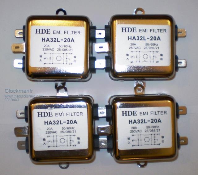 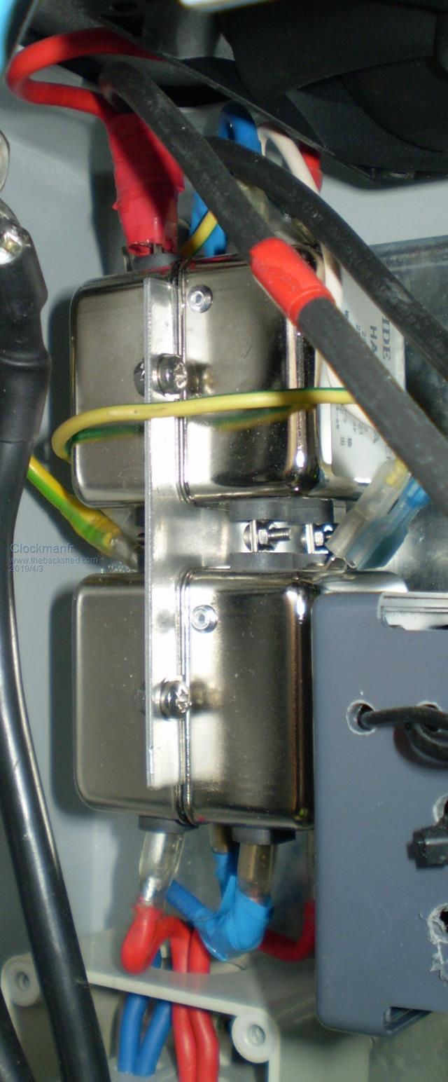 Everything is possible, just give me time. 3 HughP's 3.7m Wind T's (14 years). 5kW PV on 3 Trackers, (10 yrs). 21kW PV AC coupled SH GTI's. OzInverter created Grid. 1300ah 48v. |
||||
| ltopower Regular Member Joined: 08/03/2019 Location: United KingdomPosts: 64 |
Ah, nice... will have to sort a few out, like how thye are bolted together... thanks. I did not think the RF units could be used parallel so learnt something else and solved a problem ! My inverter is currently sat on a wooden board (no metal case) so need to sort a case out by the sounds of it... I had been looking at the common mode chokes, EMI filters, LC, LCL, etc, and was struggling to understand them all for filtering as I was recalling what Andrew had said about two types of filters, one for RF and the other to stop harmonics getting back into the inverter. Guess the RF side and LF side was creating interference in my brain and scrambling it a bit... I have been going round in circles trying to fathom how (if it is even possible) to stop the LF harmonics going back into the inverter ? Or do LF harmonics (other than the 75Hz 5uF) really matter ? What stops attached (house wiring / attached gadget of doom) capacitance from resonating the transformer with an extra 5uF at idle ? |
||||
| poida Guru Joined: 02/02/2017 Location: AustraliaPosts: 1420 |
In relation to busted FETS Thanks for the insight on destroying fets. (the game is called inverter Roulette) I have destroyed more than 100 fets, and it is nearly always after initial start up as you demonstrated tonight . I have not had another start === blowup since, I make sure that the main power capacitors are at zero voltage (short capacitor out) then charge the capacitor by zapping 48v to the supply . then switch the inverter on. My reasoning for the above is to make sure that no residual voltage, has enabled one or more fets to remain switched on cheers john I just made a test. Madness power board has one only HY4008 per leg of the full bridge. 60V DC supply. I applied 60V DC power to the Madness board, with nanoverter board always connected to power board. I measured the voltage on the DC bulk caps, from 0, to 60V in 5V steps, applying power at each step, run the inverter, stop it, discharge DC bulk caps via resistor to next voltage step, apply power, run inverter, rinse, repeat... No blowup at any voltage. I'm not sure that is good news or bad. Inconclusive test results. wronger than a phone book full of wrong phone numbers |
||||
| Tinker Guru Joined: 07/11/2007 Location: AustraliaPosts: 1904 |
I think the inverters we have built, using the outputs from the IR2110, direct into MOSFET gates, via a 5R resistor (or something) bring some issues of reliability thanks to the dv/dt voltage pulses that can damage the gate drive ICs. My idea of using 15V TVS diodes is a bandaid. It works. Me thinks my recent topic regarding gate resistors and Solar Mike's reply gave me an idea why my early attempts of inverter building ended usually in a 'bang'. Back then I was using either 4R7 or 5R6 gate resistors and driving 6 mosfets in parallel. Obviously I did not fully understand the loading effect on the driver by these paralleled resistors and just copied what I saw at various other builds. Anyway, as soon as I started using the totem pole drivers the 'bang' effect went away ( only happened when I did something stupid to other parts of the inverter). Klaus |
||||