
|

|
Forum Index : Electronics : Simple battery charger
| Author | Message | ||||
| larny Guru Joined: 31/10/2011 Location: AustraliaPosts: 346 |
Jasper, A 4V3 Zeners do not have a very shrp "knee" & have a greater temperature coefficient than a 5V1 or 5V6 Zener. As for the hystersis variance there are several factors. 1. Op Amp offset (I assume this is temperature dependent) 2. Changes to components as they age. 3. The Voh issue. Number 3 can be solved by other means, but I want to explore the CMOS options next. Thanks re the Spice issue. Len |
||||
| Warpspeed Guru Joined: 09/08/2007 Location: AustraliaPosts: 4406 |
A different approach to the whole narrow hysteresis problem would be to first amplify and level shift the measured voltage before it actually gets to the voltage comparator stage. That way, there can be a much healthier voltage swing to work with, and the switching thresholds at the comparator could even be fixed, and any slight adjustments to thresholds made to the amplifier stage. A healthier voltage swing also goes a long way to reducing nuisance tripping from any noise, especially of the preceding amplifier is given a steeply falling frequency response. I very recently did something like this myself, to make a temperature controller for a domestic refrigerator. Output from a platinum PT100 temperature sensor was only a couple of millivolts, and I wanted a switching hysteresis of slightly less than one millivolt. What I did was amplify the millivolt signal by x2500 and feed it into a CMOS Schmidt trigger that had fixed switching thresholds of roughly around two volts apart. Hysteresis ended up about 0.8mV at the sensor, and about 2v at the Schmidt trigger. The amplifier was given a very steeply falling frequency response so that any 50Hz noise pickup from mains or motor wiring was effectively removed. It works extremely well. The fridge motor cycles on and off very cleanly with a temperature hysteresis of around 2 degrees Celsius inside the refrigerator. One way to get much more definite rail to rail swings for closely defined hysteresis, would be to place a CMOS buffer after the LM358 analog chip, and use the output from the CMOS logic chip as a source for the hysteresis voltage. That will switch rail to rail very positively and be trouble free. Cheers, †Tony. |
||||
| larny Guru Joined: 31/10/2011 Location: AustraliaPosts: 346 |
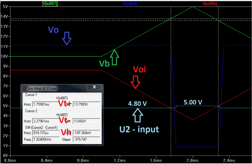
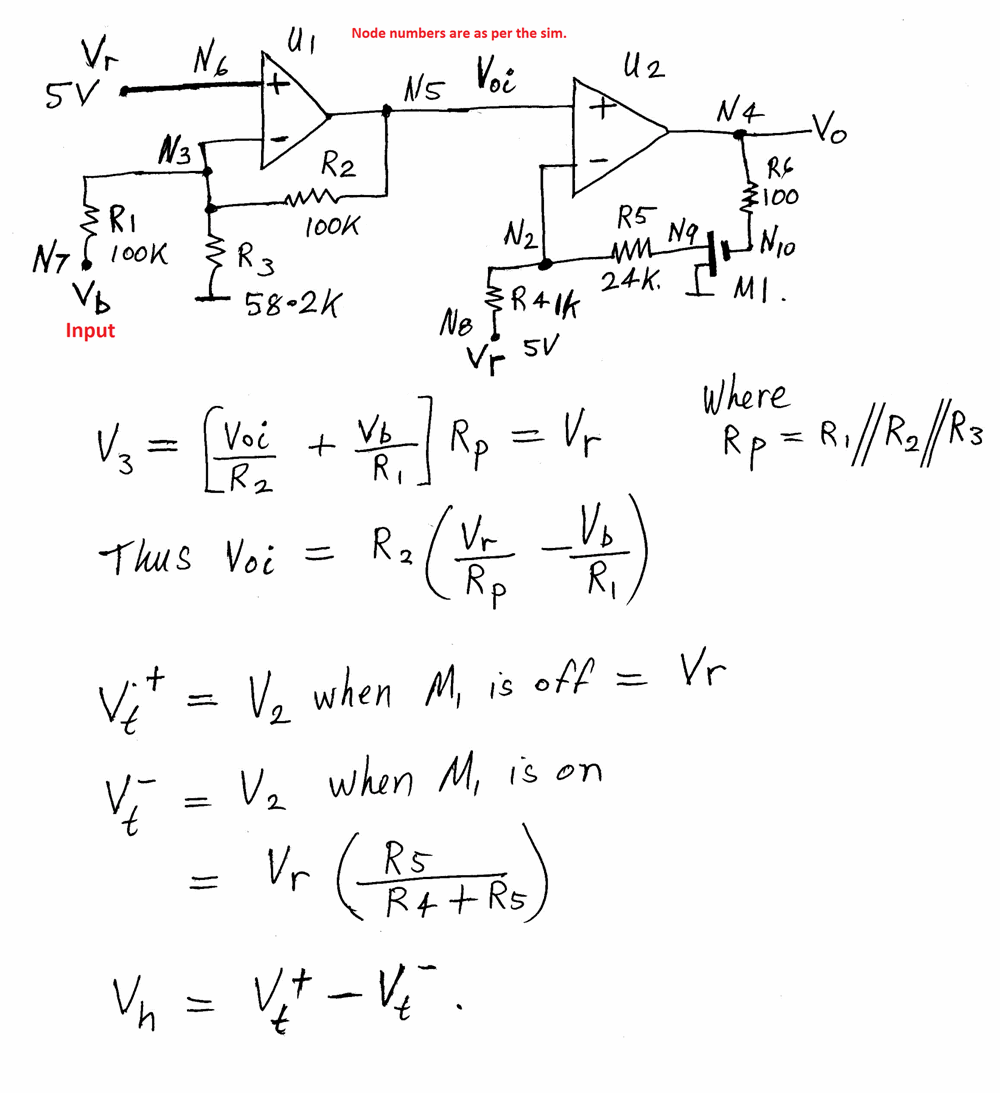
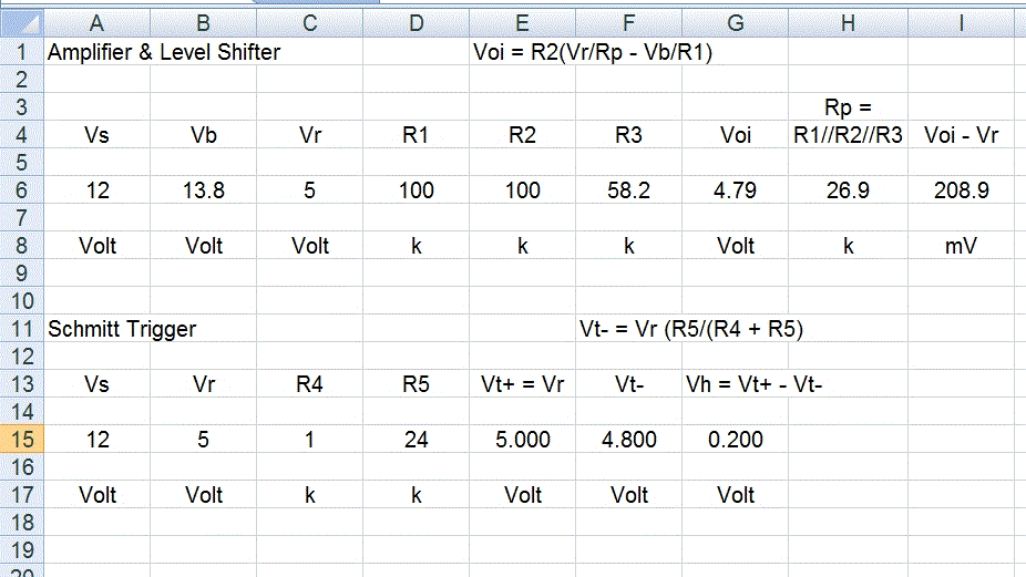
Tony. That's intereting. I did something similar last week. It was before Jasper had given me the Model for the LM358 so I used two Op Amps from the LTSpice library. The M1 MOSFET is to bypass the Voh issue & to make the Vt- (& therefore the hystersis) independent of the Vt+ setting. I also thought about using a CMOS Schmitt Trigger package, but did not persue it much. I intend to consider the use of a CMOS inverter first, ie. configure one as a ST. all the best, Len 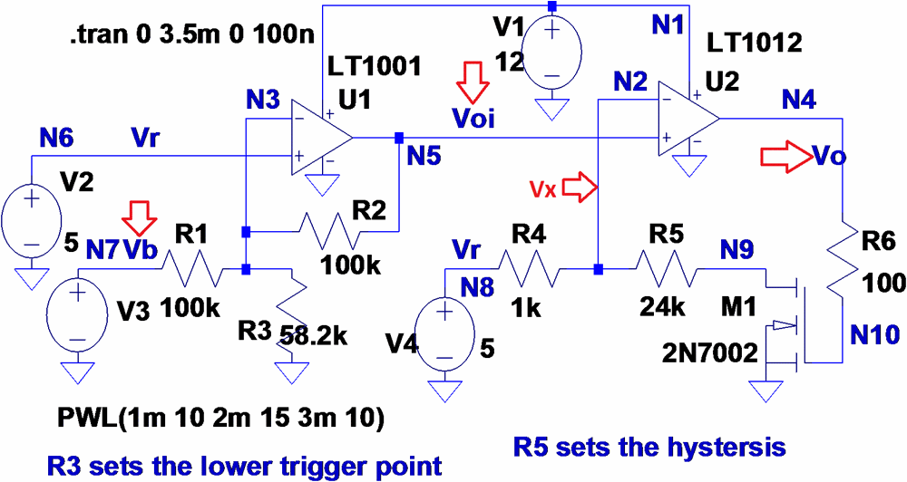
|
||||
| Warpspeed Guru Joined: 09/08/2007 Location: AustraliaPosts: 4406 |
Len, that certainly solves the wobbly LM358 problem, and gives you some hard hysteresis numbers to work with. That would be my approach, build a voltage comparator with well defined switching thresholds, then "tweak" the input voltage swing from the battery with an amplifier. With a bit of numeric experimentation, almost any switching thresholds could be achieved fairly accurately with common resistor values. Cheers, †Tony. |
||||
| SpmP Newbie Joined: 10/10/2010 Location: New ZealandPosts: 32 |
Aaaaand more fun with the real thing... SO it turns out in reality there are a number of peculiarities, suprisingly enough, not in spice 8) For some reason with the LM358 if supplied by 5v, then higher than ~4.5v dont work. In fact it looks like it doesnt change state when v+=v- super strange, or are my probes getting in the way? I am going to bump up the o/p from the 7805 to 6V and see if this becomes workeable. Also, and this may be my crap scope skills, but it seems that a 15turn precision pot (the long ones) pick up a heap of noise!, especially if only two terminals are used, and the third left floating. replacing it with a horrible cheap metal pot solved the problem... I will play with what I have got for a little this morning and see what sort of hysteresis can be achieved. I don't imagine breadboard is helping with its almost good enough connections all components sticking into the air absorbing 50Hz goodness ....right.. so if we are back to using two opamps for the hysteresis, then its probably best to separate the two circuits out from each other. The battery relay on its own as it has a voltage range 10-15, and hence needs the annoying low voltage reference... and the solar/dump controller, as it has a working rhange 12ish (more like 13) to 14. Can use a higher voltage reference, and hence less division by the... er divider. The mosftet solution is pretty clever, to adjust the 'trigger' point would it best to do this with a variable resistor at R1? Cheers. Jasper |
||||
| larny Guru Joined: 31/10/2011 Location: AustraliaPosts: 346 |
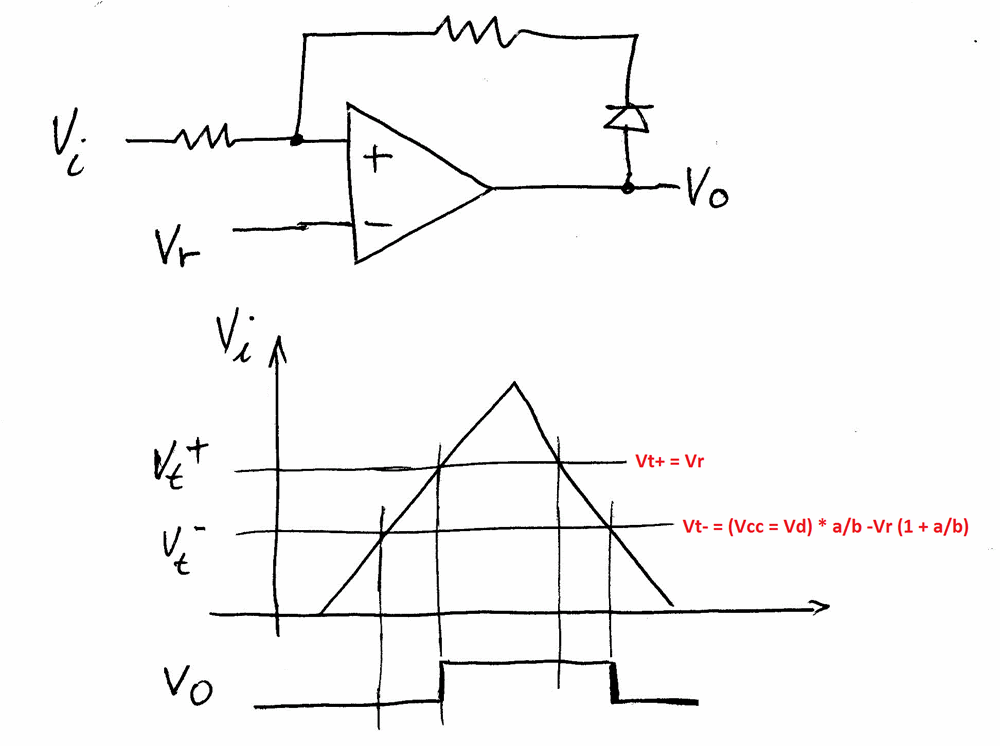
Here is another method that I have used to make the Hystersis independent. The diode is a simple alternative to the MOSFET. BUT, the diode will have a temperaturs coefficient that must be considered. Len EDIT. The answer is in the maths. The Vt+ level is set by Vr, so use a pot to vary Vr as in the extract below. R1 is accociated with the Level Shifting Amplifier. So don't touch it. 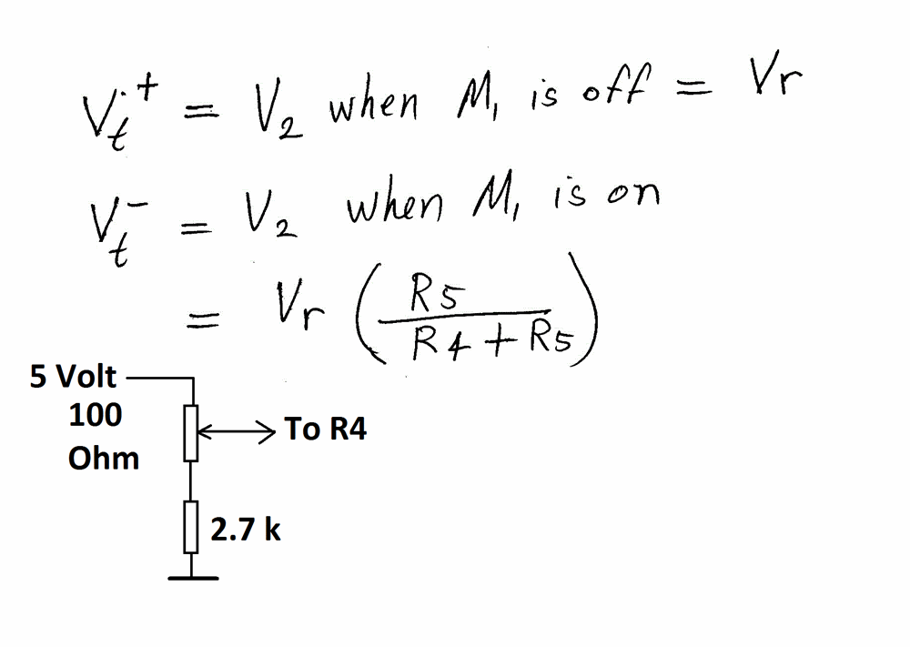
|
||||
| larny Guru Joined: 31/10/2011 Location: AustraliaPosts: 346 |
If you don't have a 100 Ohm pot, then consider one of the options below. The important point is to keep the Thevenin resistance low. I don't want it to exceed 100 Ohm otherwise it will affect the hystersis. It needs to be much less than R4. Let me know how you go as we may have to change the Amplifier resitors bt=y a small amount in order to bring the level adjustment into the correct range. Len 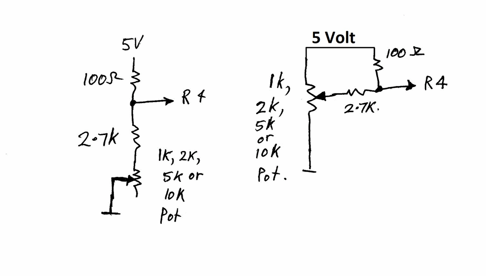
|
||||
| SpmP Newbie Joined: 10/10/2010 Location: New ZealandPosts: 32 |
Much appreciated Len! All I can do is go over the math atm as the kids are home with the flu, probably for the next few days 8) The pots mentioned in the circuit are the Vrefs as voltage dividers (not so bad) and the hysteresis selection which you had as an 82K resistor in a post on the previous page, this is the one that was causing problems. Jasper |
||||
| larny Guru Joined: 31/10/2011 Location: AustraliaPosts: 346 |
Jasper, I have attached a modified version of the Sim circuit that I think you're talking about with suggestions added. Note that putting a Pot in series with a fixed resistor gives you a finer adjustment range & also avoids having the Pot connected to the Op Amp input. Len 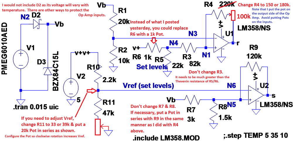
|
||||
| larny Guru Joined: 31/10/2011 Location: AustraliaPosts: 346 |
Jasper, I have been thinking about the possibly using the 555 as a Schmitt Trigger. I found the circuit below on an internet site that explains how it works as a ST. I added some notes of explanation. You should also look at the 555 Data Sheet. Len 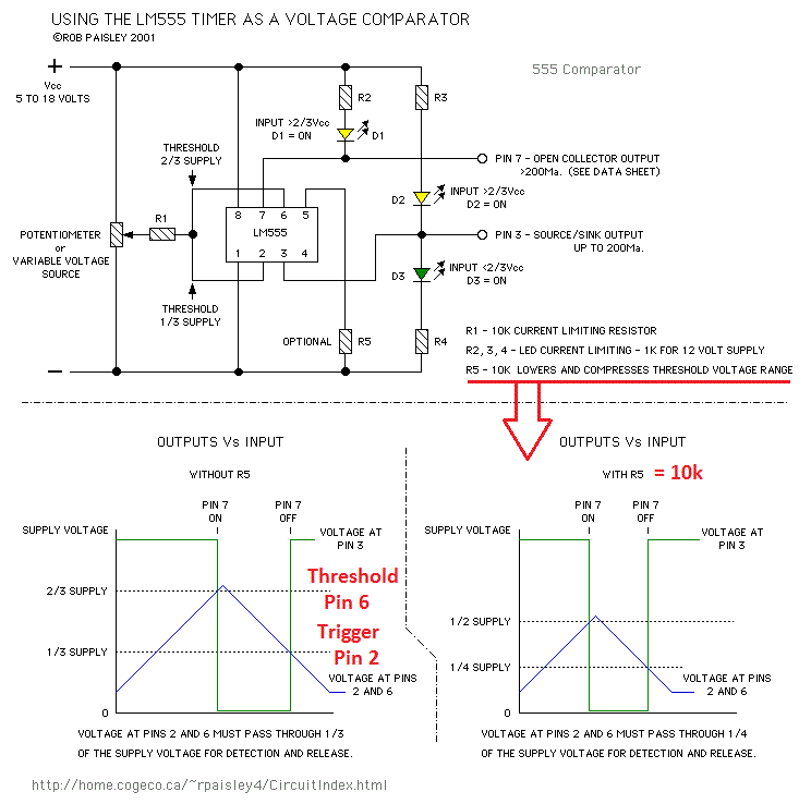
|
||||
| larny Guru Joined: 31/10/2011 Location: AustraliaPosts: 346 |
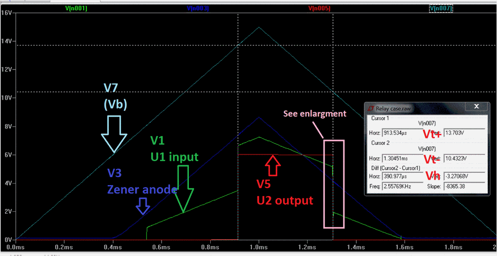
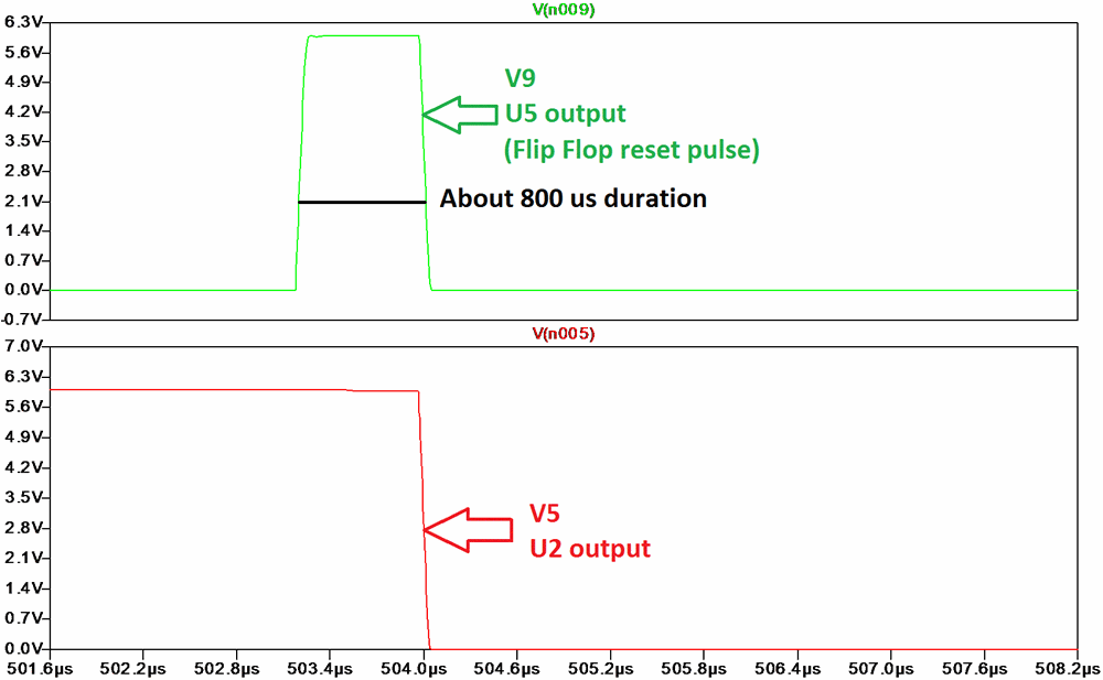
Jasper, After considering numerous options, I have decided upon the one attached. You can do both the shunt and relay cases with the one IC since the 40106 hex Schmitt Trigger has six STs in the one package. There are other types of hex Schmitt trigger such as the 74C14 etc. You donít need any input protection, since they have internal protection diodes. The relay case circuit will be very similar with only minor changes, Iíll post it either tomorrow or next day. I have used a Zener diode to shift the level in order to reduce the attenuation that would occur had I used a resistive voltage divider. Zener diodes have a low slope resistance so there is virtually no attenuation due to the Zener. U1 and U2 are configured as a Set/Reset Flip Flop. It is Set when the voltage at N1 rises to the positive going threshold of U1. The positive going threshold is determined by D1 & the R1/R3 + U4 voltage divider and the positive going trigger level of U1. When the voltage at N1 rises to the positive threshold of U1, the output of U1 goes low thus causing the output of U2 to go high & consequently shift the voltage at N1 higher than the Schmitt Triggerís positive threshold. The negative going threshold is set by D1 & the R4/R5 + U3 voltage divider and the negative going trigger level of U5. When the voltage at N8 decreases to the lower threshold of U5, the output of U5 will go high. Transistor Q1 is turned on, this Resets the Flip Flop & so the output of U1 goes high which causes the output of U5 to go low so transistor Q1 turned off & so the circuit is thus returned to the initial state where it is waiting for the voltage to rise to the positive trigger level. Therefore, Transistor Q1 is turned on a very short time, see the attachment below. Iíll post an adjustment procedure tomorrow (the threshold adjustments are independent). 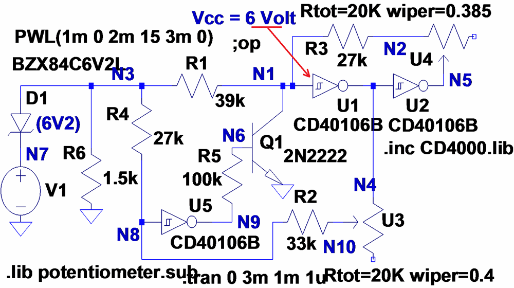
|
||||
| larny Guru Joined: 31/10/2011 Location: AustraliaPosts: 346 |
Jasper, Here is a zip of the .asc so you can run it yourself. Len 2012-05-16_133619_Simulation_zip.zip |
||||
| SpmP Newbie Joined: 10/10/2010 Location: New ZealandPosts: 32 |
OK... I have built the opamp circuit as at the top of page 5 (I have no comparators to work with atm), and have tested on breadboard, which is a PITA - re dodgy connections... and have the following observations and addendum: V+ supplied by LM317T set to 7.5V (470/2k2) With higher V+ Voh is a little higher, and to achieve a smaller hysteresis R9 is 220K. With various PSU loads and 1.8ohm resistor as a shunt I confirmed that this works reliably... I have tried it with a panel, and it seems very easy to set threshold etc. Unfortunatly the totem pole driver (and direct o/p from the opamp is not driving the logic level fet hard on, so loads of heat) Is the idea wrong, with ~6V out of the opamp, the totem pole is only giving 3.75V to the fet whether the top is connected to the rail (14.4V) or Vref (7.6V)? BC547B BC557B transistors, with 10ohm opamp to base(es) The relay side with hysteresis seems unreliable, again this could be crap connections on the breadboard... Will try more later - re fet on hard! Jasper |
||||
| larny Guru Joined: 31/10/2011 Location: AustraliaPosts: 346 |
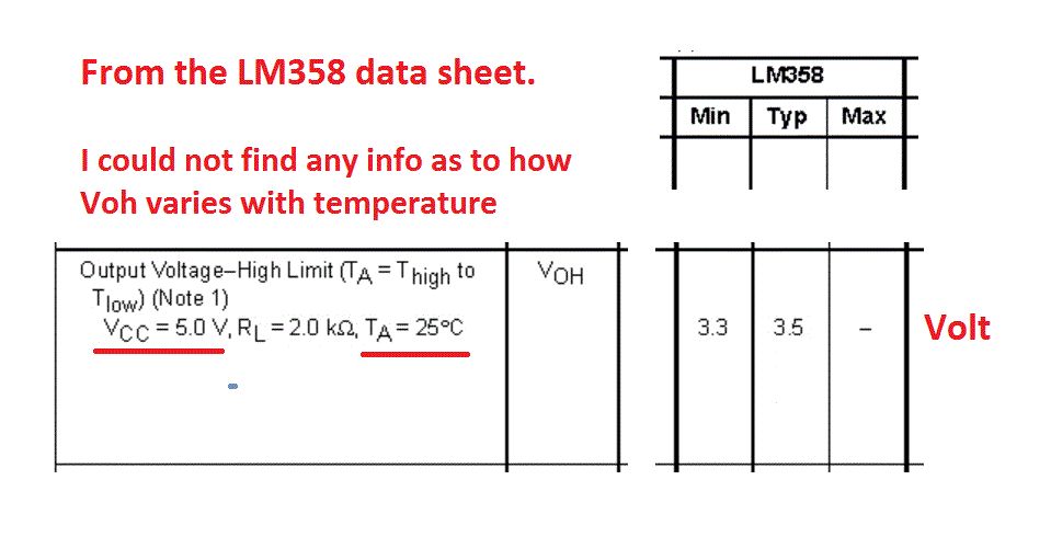
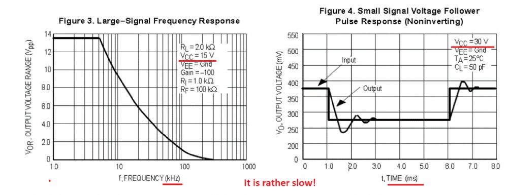
Yes, you need a better FET drive circuit. I have attached an extract from a Silicon Chip Motor Control circuit that shows their IGBT driver. Also note their Vcc is 15 Volt. You are very optimistic expecting to make it work at 7.5 Volt. That is one reason why I suggested a DC-DC Converter or voltage doubler some time ago. Also, the LM358 is slow. My recollection is that you wanted the Shunt case to work in the kHz region. Also, I could not find much info on the variation of the LM358 parameters with temperature in the data sheet. See the extracts. These are the types of reasons why I have been considering the use of CMOS. Yesterday, I conceived a better version than the one I posted above. Nevertheless, you still need to be able to drive the FET properly. A 15 Volt supply would make a big difference. It would also assist with the small hystersis you want for the Shunt case as:- 1. there would be no need to do much level shifting (if any). 2. there would less scope for temperature changes to upset the apple cart. Len 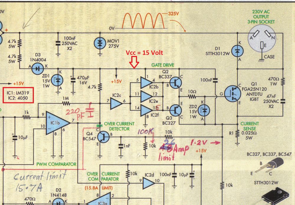
|
||||
| larny Guru Joined: 31/10/2011 Location: AustraliaPosts: 346 |
Here is a simple voltage doubler from the 50-555 Circuits.pdf that I downloaded from talkingelectronics.com 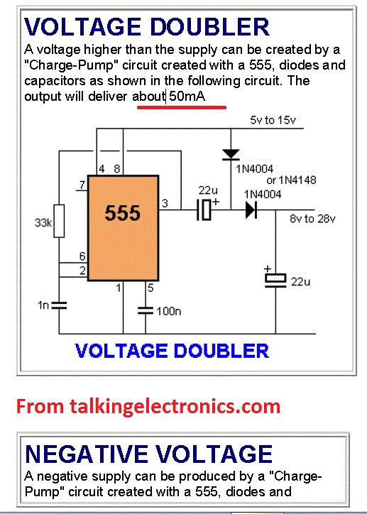
|
||||
| SpmP Newbie Joined: 10/10/2010 Location: New ZealandPosts: 32 |
Thanks Len for the continual Info. What seems to be happening with the LM358 schmitd trigger is that with a small PV panel or charge current it all works nicely. When needing to dump about 5A+ then the opamp OP and mosfet driver OP was reducing, i.e no hard switching and burning up a fet. I have had a play with the simple transistor totem pole driver (same as in the silicon shcip without the buffer amps and zener) and a LM324 based PWM generator and found, as expected, that the driver is fine (ish) at 1khz, switching hard with the fet staying cool. So it seems the only conclusion I can come to is that the LM358 based comapartor is operating in a linear fashion, hence giving up on it and going to buy some 40106's now. In terms of switching non logic level fets the nmos/pmos driver as in ghurds shunt controller looks like it can switch Vcc to the gate. On inspection of his circuit it looks like it should work, only thing is LTSpice says otherwise, damn thing... Just for reference: Ghurds controller All this just to reinvent the wheel using standard parts and a spoke shear! I think to-92 pfets and brown out detection chips may be a little hard to find in some places. What about 40106B (74HC14)? what could you scavange that off? Would a rail to rail or audio opamp be more common? Still I guess I have found that the opamp scenario is dead unless what I am seeing is a result of an undefined Voh. I would still want to drive a bit more off this circuit, such as having the overvoltage protection zener, a power good/on LED, a relay to connect/disconnect the solar panel when the power is not good... (i.e controller not connected to battery or overvoltage has blown the fuse), and of course the mosfet. In this case wouldnt a linear voltage regulator be better in place of the 6v2 zener? Still, learning how little I know is always, well, something. Good maybee. Cheers. Jasper |
||||
| Warpspeed Guru Joined: 09/08/2007 Location: AustraliaPosts: 4406 |
Jasper, The only problem with using any of the CMOS Schmidt triggers will be that the threshold voltages are not at all well specified, and will be all over the place. Plug in a different chip and the thresholds can change by a volt or two !! While these Schmidt triggers do an admirable job of cleaning up slowly moving or noisy rail to rail logic transitions, they will make a truly awful voltage threshold detector if you need known accurate switching and hysteresis levels. Cheers, †Tony. |
||||
| SpmP Newbie Joined: 10/10/2010 Location: New ZealandPosts: 32 |
Weeeeel, With a nmos-pmos driver as in Ghurds circuit the thing switches hard on/off, the fet stays cool, and the shunt resistor keeps burning my finger prints off. Sooo it looks like the LM358 will actually work with a more responsive driver! I am getting a reliable hysteresis of 150mv, and frequency of ~8khz no problem (well the wave is not very square at 8khz so could try an 324N whih is an order of magnitude faster.) Damn I burnt my desk... damn shunt loads. So success. It is pretty easy to calibrate, connect panel and multimeter, then adjust dial until you get the voltage you want. There are symmetric switching peaks, but the averaging multimeter ignores them... how nice. The larger hysteresis circuit needs some attention, I will get that going before I give up on the opamp solution for now. (as it is working 8) OK, changing R4 to a 500K pot, and making sure all contacts were good, after a real PITA callibrating I found that the larger hysteresis/relay part of the circuit is indeed reliable! All good, so It all works. Need to find a semi dead battery to test it on now. |
||||
| larny Guru Joined: 31/10/2011 Location: AustraliaPosts: 346 |
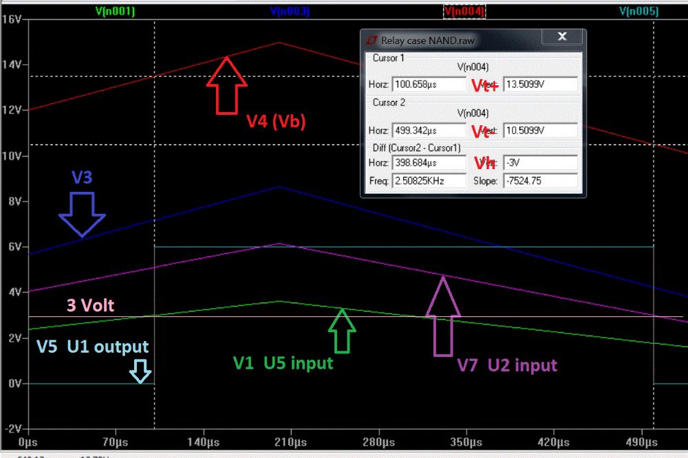
Jasper, I'm currently thinking about using 555 ICs. It has well defined thresholds & looks promising. Also, it can drive the relay directly in the "Relay Case". I agree with Tony re the CMOS Schmitt Triggers, they have a wide threshold spread. That's why I started to think about using non Schmitt CMOS gates. Here is a CMOS NAND gate option (it can also be done with NOR gates). Note that the Schmitt Trigger action is done by the Flip Flop formed by U1 & U2. So it switches very quickly. You could use either a Quad 2 input NAND Package or a Triple 3 input one. I'll post the 555 ideas later today or tomorrow. Len 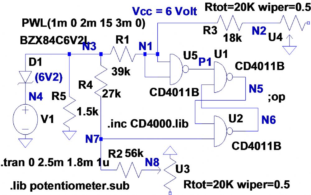
|
||||
| Warpspeed Guru Joined: 09/08/2007 Location: AustraliaPosts: 4406 |
I rather like the 555 idea, very ingenious. The 555 has rather a lot going for it, and it is a solution I had not thought of myself. It's all there. Two proper voltage comparators, well defined switching thresholds, and a set/reset flip flop, plus reasonably high output current capacity. Cheers, †Tony. |
||||