
|

|
Forum Index : Electronics : Started Buck converter project
| Author | Message | ||||
| Warpspeed Guru Joined: 09/08/2007 Location: AustraliaPosts: 4406 |
Don has come up with a very good solution. I would suggest you keep the IR2117, as it simplifies things a great deal, and you already have it. Get rid of the diode that would normally charge up the bootstrap capacitor, and connect the output of Don's small isolated dc power supply directly across the bootstrap capacitor to keep it charged to a constant +12 volts. That will give you the best of both worlds, with a minimum of extra components and circuitry. The IR2117 will then work down to zero frequency, and the buck converter will start up and run happily into either a battery, or ground a referenced load without any problems at all. Do an e-bay search for "isolated power module" There are quite a few suitable parts advertised for around five to ten dollars. Typically 9-18v dc input, 12v dc output, one watt.  Cheers, †Tony. |
||||
| govertical Guru Joined: 11/12/2008 Location: United StatesPosts: 383 |
Hi, Vin can range from 0 to 200 volts DC or higher depending on the RPM of turbine. Do you have any suggestions to protect the isolated power module? just because your a GURU or forum administer does not mean your always correct :) |
||||
| Warpspeed Guru Joined: 09/08/2007 Location: AustraliaPosts: 4406 |
That VB1212S in the picture is rated to 1,000 volts of isolation, which is pretty typical for these types of devices. It really does not need any additional protection at all. Just connect the modules dc input across the battery, and the +12v dc output across the bootstrap capacitor, that is all you need to do. Here is a link to the data sheet for that particular device, click on the PDF for the data download. http://www.datasheetdir.com/VB1212S-1W+Power-Modules There are other similar isolated power modules with different part numbers that are just as good if not better. Cheers, †Tony. |
||||
| Don B Senior Member Joined: 27/09/2008 Location: AustraliaPosts: 190 |
If your concern is the alternator/rectifier output voltage, the first thing is to look at how you are measuring it. If you are simply measuring the open circuit voltage, then you could reasonably expect it to be substantially above its loaded output, then there is also the possibility of meter overshoot. Try connecting 100 uF or more of capacitance across it and then see what you read. Even so, you will need to keep the input voltage to the DC-DC converter within its rating. In the circuit that I posted, there was a 7805 regulator between the alternator/rectifier DC output and the converter 5V input. Whatever you use as a floating power supply, you will need a similar sort of regulator to keep its input within range. There are various sorts of regulators that can do this, and maybe one of the adjustable ones set to the highest voltage that the dc-dc converter will tolerate is what you need. Be aware though that even regulators have an upper limit to their input voltage, and if your alternator's DC output is above that, then you might have to consider additional measures such as a series resistance, etc. If the alternator output voltage is really well above the desired load voltage when under load itself, then you might need to consider re-connecting its windings to parallel rather than series connect some of the windings in the same phase. Note also that, while buck converters can work efficiently with a significant voltage difference from input to output there are practical limits and, for argument's sake, having a 200 V input voltage for a 12 V output voltage would be beyond a reasonable ask. Regards Don B |
||||
| govertical Guru Joined: 11/12/2008 Location: United StatesPosts: 383 |
Hi, down sizing the PMA is a good idea. The physical weight is to great. I will post results when available. Thank you to all for the very valuable suggestions. just because your a GURU or forum administer does not mean your always correct :) |
||||
| govertical Guru Joined: 11/12/2008 Location: United StatesPosts: 383 |
Hi, I exchanged the IRF510 with a IRF540 and I am unable replicate the results shown in the last video. It is a puzzling situation. It may require a different bootstrap capacitor or some other solution. I am unable to continue until a solution is found. The circuit will function with a lower load but does not work with 50 watt load. The oscilloscope shows the IRF540 starts to turn on then very quickly turns off, then the Vin gains magnitude and the 555 timing signal shuts down. Comments welcome. just because your a GURU or forum administer does not mean your always correct :) |
||||
| Warpspeed Guru Joined: 09/08/2007 Location: AustraliaPosts: 4406 |
A bigger MOSFET should have no effect on the functionality. It sounds as if one or more components may now be faulty, but I have no idea what. Cheers, †Tony. |
||||
| govertical Guru Joined: 11/12/2008 Location: United StatesPosts: 383 |
Hi, new test circuit based of information received and suggestions. Basically it is the same circuit as before with a blocking diode added at the plus battery terminal and a voltage pump for the bootstrap capacitor. Vg - Vs > Vthreshold , 20 - 12 = 8volts. If it works the mosfetís can be paralleled and the control circuits can be duplicated for increased current output. I apology for jumping all over with this project. I was so happy with the results driving a resistive load I lost focus of what I am trying to achieve. I am concentrating all my efforts now to interface the working circuit to charge a 12 volt battery. I have not tried all the suggestions but the problem has been traced to the bootstrap not charging, that has been suggested by others. Thank you for all the help I have been receiving and comments are welcome. just because your a GURU or forum administer does not mean your always correct :) |
||||
| Warpspeed Guru Joined: 09/08/2007 Location: AustraliaPosts: 4406 |
The blocking diode after the buck regulator choke will certainly isolate the battery at initial startup. But when the MOSFET is off, the source voltage will then just be left floating. It needs something to pull the source right down to ground, because that is also the charging path for the bootstrap capacitor. Twenty volts is getting dangerously high for the bootstrap supply voltage. The MOSFET gate voltage is only rated to twenty volts maximum. If you start popping MOSFETS, that will very likely be the reason why. Twelve volts is ideal, fifteen getting rather high, and twenty volts is extremely dangerous. Cheers, †Tony. |
||||
| govertical Guru Joined: 11/12/2008 Location: United StatesPosts: 383 |
Hi, in the past I received a suggestion to attach a 100k resistor between the gate and ground to make sure the mosfet turns off, would that provide a path to return Vs to zero volts? Thank you for information. just because your a GURU or forum administer does not mean your always correct :) |
||||
| Warpspeed Guru Joined: 09/08/2007 Location: AustraliaPosts: 4406 |
No. The problem is not turning the MOSFET off, but turning it on. For that to happen the bootstrap capacitor needs to be charged to maybe 12 volts. The bootstrap capacitor can never charge up at all while the negative end (also connected to the MOSFET source) is left totally floating. The negative end of the bootstrap capacitor MUST BE GROUNDED at least momentarily for it to charge up. Cheers, †Tony. |
||||
| govertical Guru Joined: 11/12/2008 Location: United StatesPosts: 383 |
Hi, I am thinking about adding a second blocking diode. Would a zener and LED configuration be able to pull Vs to ground during the off cycle? Any comments will be greatly appreciated. 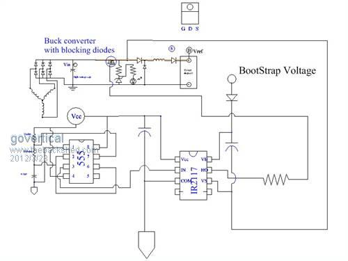
just because your a GURU or forum administer does not mean your always correct :) |
||||
| Warpspeed Guru Joined: 09/08/2007 Location: AustraliaPosts: 4406 |
No that will not work. One way to do it would be with a sufficiently large fully discharged capacitor, with an associated bleed down resistor for initial startup. Once running, the back EMF from the choke will keep it running. The other much better solution, is to power the bootstrap capacitor continuously from a fully isolated independent power source. Cheers, †Tony. |
||||
| govertical Guru Joined: 11/12/2008 Location: United StatesPosts: 383 |
Hi, I was able to find all the needed parts to make all the required connections to interface the circuit to a 12 volt battery. I am using two bench power supplies, one to power ICís and the other for Vin. I had just a LED and 22kohm resistor from the mosfet Vs to ground and the mosfet was turning on and off when connected to the battery. With a capacitor at the output of the circuit no current would flow into the battery. I removed the capacitor and I was able to measure 0.14 amps flowing into the battery. I had attached a variable resistor to the 555 to be able to test different duty cycle, I adjusted the variable resistor to low and the 555 fried, so I have to purchase some replacements before I can continue testing. Without the valuable suggestions I would not have been able to get the circuit developed to this stage, Thank you. I will post more test results after I replace the 555, thanks again. photo of IR2117 output and input of the inductor 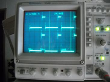
photo of IR2117 output and output of the inductor with no cap across battery 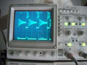
photo of IR2117 output and output of the inductor with cap across battery 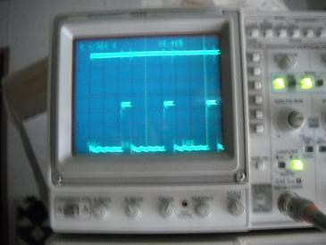
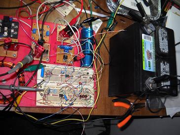
just because your a GURU or forum administer does not mean your always correct :) |
||||
| Warpspeed Guru Joined: 09/08/2007 Location: AustraliaPosts: 4406 |
That is quite likely if the PWM duty cycle and input voltage produce an AVERAGED output voltage below the battery terminal voltage. If the battery voltage is twelve volts, you need a higher voltage than that to charge it. Say 50% duty cycle and 28 input volts, or 33% duty cycle and 42 input volts for example. Cheers, †Tony. |
||||
| govertical Guru Joined: 11/12/2008 Location: United StatesPosts: 383 |
http://www.youtube.com/watch?v=-UalBvsoTuE&feature=youtu.be New video of circuit operation with PMA and battery load New video of circuit operation, I am manually operating the PMA. 12 volt battery as load. Waveform is Vs of N channel mosfet. Vin = 20 volts at highest RPM, current into battery 0.75 amps at highest RPM. The waveform is not what I expected, at this time I am unable to explain results. It looks like I have to inverter the control signal. comments welcome just because your a GURU or forum administer does not mean your always correct :) |
||||
| govertical Guru Joined: 11/12/2008 Location: United StatesPosts: 383 |
Hi, when I use the PMA to test the circuit I get very different results from the results obtained when using the just the bench power supplies. just because your a GURU or forum administer does not mean your always correct :) |
||||
| Warpspeed Guru Joined: 09/08/2007 Location: AustraliaPosts: 4406 |
Probably because the bench supply is a stiff voltage source, and the PMA is more like a current source. When you load the bench supply, the regulated voltage stays the same. When you load a PMA, the voltage will drop significantly. Cheers, †Tony. |
||||
| govertical Guru Joined: 11/12/2008 Location: United StatesPosts: 383 |
Hi, I found a paper showing different converter topologies. CUK converter and SEPIC converter are operated by a low side mosfet on page 10. They maybe easier to interface with a battery bank using blocking diodes. Comments welcome. http://ethesis.nitrkl.ac.in/2640/1/Sriharsha_B.Tech_Thesis.p df just because your a GURU or forum administer does not mean your always correct :) |
||||
| Warpspeed Guru Joined: 09/08/2007 Location: AustraliaPosts: 4406 |
You only need the blocking diode and output capacitor as part of the "kick startup" for the bootstrap capacitor with the existing circuit. It is a rather unusual problem that requires an unusual solution. If you use a fully isolated power source to maintain a constant voltage on the bootstrap capacitor at all times, the blocking diode, capacitor and bleed resistor will not be required. If you can fully comprehend all the formidable design equations of designing a CUK or SEPIC converter, along with designing suitable magnetics for it, go right ahead. It will be far from easy. A buck regulator is much simpler, much easier to get going, and unlike a CUK, the choke is pretty simple to design (it can never be made too large), and it will be more efficient at higher power levels. With a CUK you are pumping packets of magnetic energy stored in the choke, and choke design is quite critical, or it simply will not transfer sufficient power to the output. If the magnetics are not designed correctly the switching device will very easily blow up from the high current spikes produced by magnetic saturation. Choke too big = full output power can never be reached. Choke too small = instant death to the switching device. Choosing the correct magnetic core, correct number of turns, and correct air gap, for the voltages and frequencies you decide to use is not a trivial problem. Cheers, †Tony. |
||||