|

|
Forum Index : Electronics : Question regarding capacitors?
| Author | Message | ||||
| WindyMiller Regular Member Joined: 05/04/2011 Location: United StatesPosts: 62 |
Len, I had figured out that the cap would need to be at least 1 farad and had given up on the idea this past summer. I have never seen any 1 farad cap that can withstand say 400 volts or better. I will have to figure out the best combination of several large caps to equal 1 farad. I have seen 1 farad caps that would work for the 12 volt battery charging side and am interestined in the following below for that reason? In the event I find a cap suitable? I am still interested in knowing what you have to offer regarding the following? If you need to use a capacitor (ie. if the flywheel idea is not viable) then I'll add some simple circuitry to cope with the charging current, etc. I am interested in knowing about this simple circuit? I will checkout the other links in the coming days. The one I have seen and posted on regarding another project. My concern with “the back shed” forum is that, as far as I know, I’m the only electronics engineer contributing. I had come to that conclusion some time ago from reading some of the post and the responses given. Also some of the people in the know have moved on as I do not seem them actively contributing any more sadly. Sparweb is the name that comes to mind here as he was the expert on induction motors and the magnet conversions for wind turbine use. I have several questions for him if I find a way to contact him? If you connect diodes as shown in the drawing, this will introduce a voltage drop of 1 Volt or more - depending on the current. I had already figured out that there would be a drop, and have already considered schottky diodes for that reason. This will not make much difference in the 110 Volt case, but it will in the 12 Volt case. So I suggest you consider Schottky diodes in lieu of normal ones. These have a lower voltage drop, but there will be still some effect. Diode D1 will prevent the issue that you raised regarding draining the battery in the 12 Volt case if something is left plugged into the outlet when the alternator is off. Diode D2 will reduce the voltage has a voltage regulator. Is it possible to adjust the voltage regulator to compensate? The unit is sealed and is inside the case of the unit. This is the only thing that I have seen that could raise the voltage up again. http://www.smartgauge.co.uk/alt_mod.html http://www.smartgauge.co.uk/alt_float.html I would like to incorporate all of this into a little regulator box if possible? In the end I want to keep things relatively simple when it comes to the final design? Less things to go wrong and cause some other headache later. In other words I do not want to deviate too much from the way a standard Alt VR would be constructed if possible? I have been thinking about your issue with the engine stalling when battery charging. I believe what you need is a current monitor that will change the alternator field current in order to limit the current going into the battery. I had come across this article while searching the web http://www.4shared.com/office/bbbJYluY/Build_your_own_12vdc_ engine_ge.html Anything I do or make will need to fit in with my end goal I mentioned in my regulator post and above. For that reason I have always considered the field controller to revolutionary? I had a look at your PDF attachments and will research the devices mentioned. The one device regarding the hall effect sensors has been a long standing question of how do they do that since I came across a drawing of an alternator so fitted. Len, You had mentioned in an email you have other ideas that could be useful? I am interested in all ideas and theory that could help solve this problem? The cap idea is slowly dying a slow death for obvious reasons stated here in this topic. The idea started out as a simple way to decouple the alt from the loads across the plates of the cap. However it looks like there is other things that will come into play and destroy the whole theory. This is the fun and fustrations of engineering. As they say nothing is ever simply simple. Robert |
||||
| larny Guru Joined: 31/10/2011 Location: AustraliaPosts: 346 |
Robert, I'll address the other issues later |
||||
| yahoo2 Guru Joined: 05/04/2011 Location: AustraliaPosts: 1166 |
Afraid I don't have time to contribute, I am still trying to finish the last of my harvest, lot of long hours.  
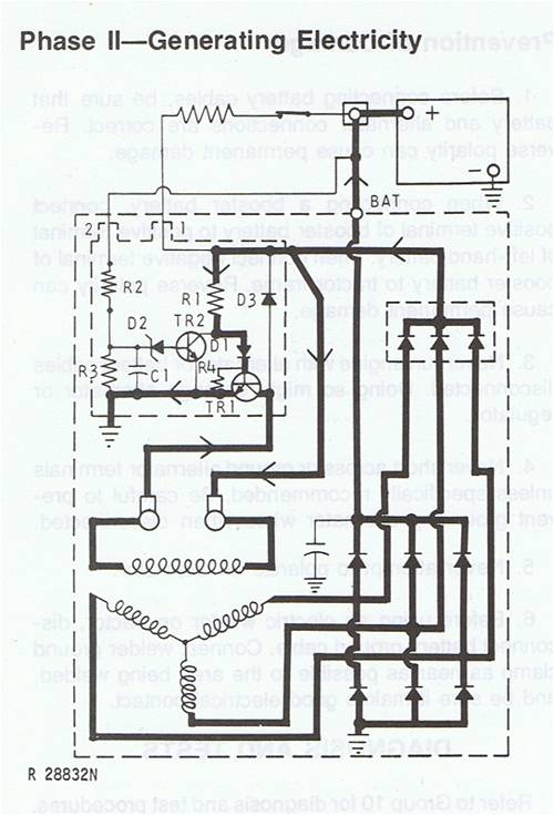
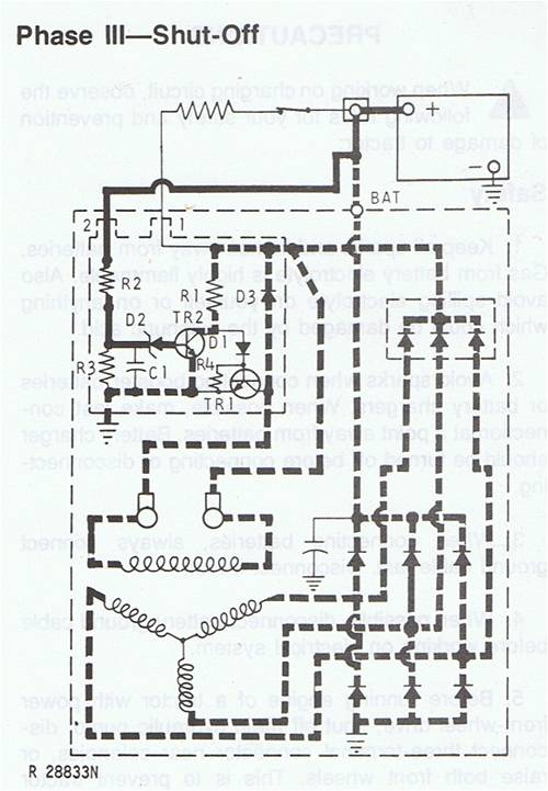
this is a simplified diagram of the delco 12Si 3 wire regulator circuit and alternator. R3 is very high resistance to prevent battery drain. R3 and R4 produce a voltage differential to allow the transistors to trigger. D2 is a zener diode that switches TR2 at critical voltage sourced from terminal 2. I don't know how fast it switches, could be anything from 100 to 2000 times a second? Adjusting the voltage at terminal 2 changes the % of "on" time. Almost every delco variation from the same era is based on this. The diesel engine specific alternator is wired delta and is 71 amps at lower revs. Very simple conversion Terminal 2 controls charging voltage, this is wired to Bat + internally on a 1 wire alternator making it hard to adjust the alternators charging characteristics. I don't like some of the aftermarket 100 amp knockoffs as the cooling on these is not good enough for heavy work. yahoo I'm confused, no wait... maybe I'm not... |
||||
| larny Guru Joined: 31/10/2011 Location: AustraliaPosts: 346 |
Thanks for the quote mate, hope your harvest is going well. In the circuit you posted, what is the point of the resistor that is to the left of the battery & what looks like a Circuit Breaker? Len |
||||
| yahoo2 Guru Joined: 05/04/2011 Location: AustraliaPosts: 1166 |
Just had 20 mm of rain so its an enforced holiday for a couple of days while it dries out. The "circuit breaker" is the key switch and there is some resistance built into the wire. So transistor1 is triggered from the key when the ignition is on and the alternator is stopped or the revs and voltage are too low to switch the transistors from the triple diode pack. (diode pack is pictured between the battery and the bridge rectifier). I had a quick look at mine and priced the parts to recondition it, I reckon its not worth the effort, I might get a fresh one from an American 4x4 importer.(or fit a bosch) the old Delco's don't like a lot of vibration and dust. yahoo I'm confused, no wait... maybe I'm not... |
||||
| larny Guru Joined: 31/10/2011 Location: AustraliaPosts: 346 |
Thanks mate, I understand now. Len |
||||