
|

|
Forum Index : Electronics : Op-amp charge controller
| Author | Message | ||||
Downwind Guru Joined: 09/09/2009 Location: AustraliaPosts: 2333 |
Yes both voltage regs will work fine, Ones (78L08) just a little smaller in size and has a lower mA output. I think most have used the LM7808 reg as more easier found. With your car relay you found, just check that it has Nc and No. contacts as many car relays dont have the Nc terminals. Is this to be used for solar or wind control. Pete. Sometimes it just works |
||||
| Bub73 Senior Member Joined: 10/12/2009 Location: United StatesPosts: 116 |
Here is the pics and pin out of my latest board; this isn't a vero board. 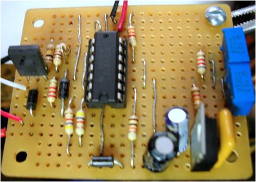
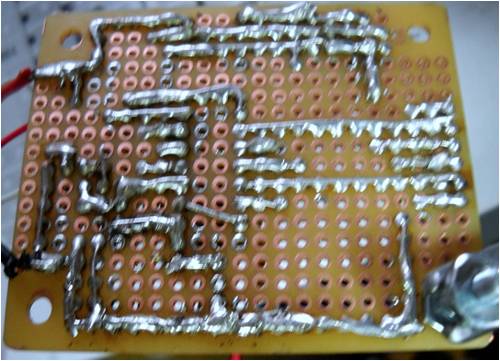
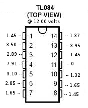
Bob |
||||
Downwind Guru Joined: 09/09/2009 Location: AustraliaPosts: 2333 |
Good work Bob, I notice you have also used a 10K resistor for R1. My circuit would not work with a 12K as R1 and i needed a 10K. Have you tried the circuit with a 12K as R1. I thought it might have been that i was using 9v reg. that i needed the lower value for R1. I am wondering if Georges circuit will work if he changes R1 to 10K......worth a try. Bob could you do a voltage pin test at 15v or the dump on voltage you have set. Pete. Sometimes it just works |
||||
| Bub73 Senior Member Joined: 10/12/2009 Location: United StatesPosts: 116 |
I haven't tried it with a 12K yet, maybe on the next one. I'll try to get a 15 volt pin out before I put it in the case. I've got the dump on set at about 14.7 off at 13.0 on my Fluke 8025; but I can bump my hp 0 to 30 supply up to 15.0 with the fine adjust no problem. Take me longer to do the graphics than the test. Bob |
||||
Downwind Guru Joined: 09/09/2009 Location: AustraliaPosts: 2333 |
[quote]Take me longer to do the graphics than the test. [/quote] Aint that the truth...I find the same. You should be able to just change the figures on the previous graphic. The higher voltage pin test is just to see the pin voltages when the circuit has tripped the dump. So if you are set to 14.7 than take the readings at 14.7 to 14.8.(dump on) Your readings look about the same as mine. Pete. Sometimes it just works |
||||
| Bub73 Senior Member Joined: 10/12/2009 Location: United StatesPosts: 116 |
@Pete; Dump on at 14.7 raised it to 15.00 with my power supply, no change to the trim pots. This should make a handy reference for trouble shooting this project.. 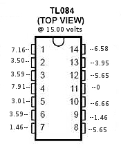
Hope we didn't lose George It's late here Bob |
||||
| Bub73 Senior Member Joined: 10/12/2009 Location: United StatesPosts: 116 |
Just rechecked my pin 1 reading at 15.00 volts; 7.16v much higher than yours, hmm going to bed check some more tomarrow. Bob |
||||
Downwind Guru Joined: 09/09/2009 Location: AustraliaPosts: 2333 |
Hi Bob, Yes my error on op1 at 15 volts. I rechecked the pin and it should have been 8.2v at the point the dump switches on. So in the same ball park as your circuit. I have edited my information now to be correct. Thanks for your involvement in all this. Pete. Sometimes it just works |
||||
| adonis Regular Member Joined: 13/02/2010 Location: SwedenPosts: 42 |
|
||||
| adonis Regular Member Joined: 13/02/2010 Location: SwedenPosts: 42 |
oops. forgot to write anything. what do you mean with this no and nc? do you mean that it should be a swithcing relay? it is, and i will use for wind control, so i will be able to swich between charging the battery and dump load. is this what you were asking? /jonathan |
||||
Downwind Guru Joined: 09/09/2009 Location: AustraliaPosts: 2333 |
Nc = Normally closed and No = Normally open. This refers to the switch contacts within the relay. With no power connected to the relay the internal switch contacts will be in the Nc or Normally closed state and No will be not connected to the common terminal. With the relay powered the common terminal will be connected to the No terminal, and Nc will be now not connected to the common. Often the auto relays only have a common terminal and a No terminal. Some have both No and Nc plus a common terminal. I was asking if the relay you have, has just No and common, if so its no good for a wind application. To put it plainly do the relay have, 4 terminals or 5 terminals. 5 terminals is good and is what you need. Pete. Sometimes it just works |
||||
oztules Guru Joined: 26/07/2007 Location: AustraliaPosts: 1686 |
[quote]Well Oz deconfuse me?? Hope its enough information. Pete.[/quote] Yes, thanks Pete. Your tireless work has yielded results. It does appear that hysteresis is not provided by the 10k pos feedback resistor. As the voltage drops back from turn on, the voltage on non inverting input op3 is 6.25 at HV turn on. It is driven higher at 16v by the diode output from op2 to 7.2v, but stays at 6.25 the moment op2 goes low. It holds 6.25 until 13v, even though the voltage drops from 15v to 13v. So there is no change on the input op3+... other than the latching voltage driven from op3 output to op3+ via the 10k resistor. So there is no discernible lowering of the 6.25 as there would be if there were a hysteresis driving the changes. It is driven by the low impedance outputs of op1 and op2. They swamp the feedback voltage completely. There will be a little academic variation near cross over.... but for all practical purposes, no hysteresis from this feedback resistor. It is provided by the op1 and op2 settings. It is now obvious that the 10k feedback is responsible for the holding on and off of the op3 at different times. It holds it stable within a few hundredths of a volt.... so it looks like my original supposition is fairly right. In this instance, I think we can say that because of the way the figures change so sharply, we can pretend that these op amps are acting a bit like sloppy logic devices. I find it easier to predict the outcomes by using this fuzzy logic anyway. You should probably work out the gain and slew rates and a whole swag of other characteristics..... but I aint that smart 
Thanks for the hard work Pete. You are a sucker for punishment. ............oztules We should be all deconfused now. Edit: Just looked at your figures again... 2/100th of a volt for full voltage swing.... pretty tidy logic really  Village idiot...or... just another hack out of his depth |
||||
| GWatPE Senior Member Joined: 01/09/2006 Location: AustraliaPosts: 2127 |
The cct behaves like an RS latch. The 10k positive feedback in conjunction with the diode create the latch, as oztules has pointed out. It is set by the high opAmp, and reset by the low opAmp. The hysterisis is purely the difference between the high and low setpoints. The same function in say micro coding would be looppoint: test for voltage if voltage higher than highset then relay output ON if voltage lower than lowset then relay output OFF. goto looppoint A similar function can be made with logic gates. Gordon. become more energy aware |
||||
| Gizmo Admin Group Joined: 05/06/2004 Location: AustraliaPosts: 5078 |
This has generated a lot of interest. I've just retrieved my controller from my old place, R1 is 10k! The original veroboard was correct, I've changed the circuit and veroboard on the web site to 10k. The two trim pots form part of a voltage divider, fed via the 12k(R2) from the 8v supply, and the 8.2k to 0v. This gives the pots an adjustment range from 2.6v to 4.2v at the opamp inputs. Dont forget the two 10k pots are in parallel, so its a 5k resistor in our voltage divider from 8v to 0v The combination of the 10k(R1) and the 3.3k to ground, give a opamp input voltage range within the pots range of adjustment, for a typical 12v charging battery. Eg, 12v = 3 volts at the opamp, 15v = 3.7v at the opamp. It was designed like this so the pots have a good range of adjustment over a voltage between 10.5v and 16.9v, about 6 volts sweep, so a multiturn pot isn't needed ( but a steady hand might come in handy for us oldies ). I used a 8 volt reg to make sure it still delivered a accurate reference voltage even if the battery dropped below 11 volts. A 9v reg could be used, but the 12k(R2) should be changed to 15k to give the same range of adjustment on the pots. Yes the 3rd opamp is set up as a latch, and the 4th opamp is a buffer. When I threw this curcuit together I chose the TL084 becasue its easy to find and cheap, plus has a high input resistance. The high input resistance means I didn't need to take take it into account when I was selecting the resistors for the voltage dividers. I should ad I didn't put a lot of thought into the component values. I just used some basic voltage divider maths and a diode or two. I was also never happy with the BD139 as a driver, I would have prefered a MOSFET, but again price and availability meant a good old reliable BD139 was used. I'm not sure the 2.2k and 1k are the best values to use on the base, but it seams to work reliably. Glenn The best time to plant a tree was twenty years ago, the second best time is right now. JAQ |
||||
| adonis Regular Member Joined: 13/02/2010 Location: SwedenPosts: 42 |
yes, i just did the same calculations on R1, but i choosed to use a 4k instead of 3,3k below R1. this gave me the reference voltage (between 12k and 4k) 3,58V at 15V battery voltage, and 2,93V at 12V. well whithin the range of the trimpots. so a mosfet would be better? i have a buz102s (gathering scrap as mentioned before) do you think this will do? regarding the OPamp, could any voltage comparator (like ha17339 or dbl 339) work in the same way? ofcourse after recounting the resistors.... the main issue should be OPout voltages at high and low? let me also take the opertunity to complement you on this controller, it is cheap, quite easy to make and simple enough to undestand. very nice! im thinking of replacing the high trimpot with one from some music ecuipment, with a wheel on the outside of the box. that way you could change the settings, and choose to connect the dump load at for example 13,2V when the battery is not beeing used, just maintained... /jonathan |
||||
Downwind Guru Joined: 09/09/2009 Location: AustraliaPosts: 2333 |
Thanks Glenn, You confirmed my thought about R1. I hope George is still keeping an eye on the 4m and changes R1 to 10k as his circuit might work for him too as mine did with R1 as 10K. Jonathan, As for the external adjustment i would not go that way, as if it gets bumped you are in instant trouble. It would be better to use a second trimmer and a switch that way you would always be in a safe operating range. With the use of the 339 etc i can not see any reason they can not be used, but as for the circuit design needed thats a whole different matter. The best way i think is to have a go yourself and workout the circuit. A bit of trial and error i think is the best way and teaches you a lot. It is the way i construct things a lot of the time. You can figure every thing you like on paper but it dont mean it will work in circuit. You appear to understand the math (better than me most likely) so have a go. Then you can post the circuit design here for others to follow. I spend many hours designing circuits for others and feel if you want to reinvent the wheel have a go yourself. I dont have the time to redo what Glenn has already done, but will offer help if you need it. Recycling Ic's is something i learnt a long time ago not to do, unless you get the circuit to work with a new one first then swap the ic's over for the junk ones. If it still works after you are lucky. At times they can have basically the same part number but operate completely different. I know this should not be the case but have been caught too many times. With many of hours down the drain. Pete. Sometimes it just works |
||||
| adonis Regular Member Joined: 13/02/2010 Location: SwedenPosts: 42 |
thanks pete. regarding the bumping, i dont think that will be a problem. this turbine prototype i hope to succesfully assemble (i have scored a LG washing machine with an engine similar to your F&P) will be used at my family country house. the electronics will be locaded in an addic in the barn. spider web and mices will probably be a bigger problem... i will use the power from the battery to charge some battery powertools, and if the energy produced is enough it will also power a small refrigerator. regarding the new circuit: no, i dont think i will improve the one Glen has made, the idea was rather to collect enough information for others to figure out how to assembly their own controller, using available IC. but you are probably correct about not recycling, the components is maby fairly cheap and easy to get a hold of even in uganda. when i already have your attention: do you think the controller will be suitable for water turbine purposes as well? (microscale) i cant see why not... regards /jonathan |
||||
Downwind Guru Joined: 09/09/2009 Location: AustraliaPosts: 2333 |
I see no difference in what energy source drives the generator as the output power will need to be controlled just the same regardless if its wind, hydro or petrol engine driving the generator. If its solar than no dump load is required as you can have solar disconnected without a problem but generators should be loaded at all times as a rule of thumb. So yes the circuit will suit all the above. What voltage are you intending to set the geni up for. Some time back there was a large discussion on the fieldlines forum about wind generators for 3rd world countrys and it was agreed in the end that solar was a much better and cost effective option and if i remember correctly a project went ahead with solar. There is to much to go wrong with wind and hydro in remote locations and is not as effective as you might think. Solar and led lighting etc is the way to go and you also have half a chance to get big bussiness involved with sponsership being a known factor. No one will sponser a pile of junk that might work and might not. Sponsers want to know their money will make a difference and know where and how it is being spent. It is much easier to ask for donations of batteries and solar panels etc compared to old washing machine parts and recycled junk. Besides the shipping costs will be much less and more productive. Good luck either way. Pete. Sometimes it just works |
||||
| George Newbie Joined: 07/02/2010 Location: CanadaPosts: 8 |
Pete & Glenn, I've been watching the forum, and the new board is together, I just haven't posted the pics or tested it yet. I'll be switching R1 tomorrow when I get a few minutes. This time around it looks more professional. I'm glad to see all this discussion and some minor corrections and clarifications regarding the project. I think the end result of all this will be a project that is much easier to understand and build, making it a better asset to the site. George George |
||||
oztules Guru Joined: 26/07/2007 Location: AustraliaPosts: 1686 |
Adonis, here is a discussion using the 339 as a dump controller. It is simpler than Glens circuit, and was simply to demonstrate the simplest controller for 12v to 100v. (change zener for 12v) It uses a positive feedback resistor in the style that Gordon referred to to give hysterisis range. It has two pots.... not for high and low, just for high cut in, the hysterisis takes care of cut out, the second one is to fine tune the voltage cutin point... ie course and fine for the wide range it operates over. I also discuss the use of 339 chips, and the pull up resistor problem. The original circuit from Methanolcat was using the 339 without the pull up, and thats why the discussion ensued.... how to get hysterisis in the circuit. It used 4 stages of dump voltages, so needed a single op-amp solution, or it would have been unweildly needing 4 for each stage (Glens). There is a third pot for demonstration purposes to set hysterisis. This one is probably the most useful, the others were discussion circuits. 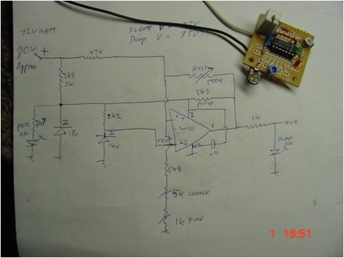
You can use any op-amp/comparators you want, just need to check the inside circuit of the chip to find out how the outputs work. .............oztules edit: took out some duplicate stuff  Village idiot...or... just another hack out of his depth |
||||