
|
|
Forum Index : Electronics : Mab1's wiseguy inverter build - transformer options
| Author | Message | ||||
| mab1 Senior Member Joined: 10/02/2015 Location: United KingdomPosts: 282 |
Thanks! That's a full answer.  looks like I'm getting ahead of myself again:- I'm putting together a digikey order and was trying not to miss anything i need - but if i follow your advice it's probably best not to buy any big caps now:- i won't want huge capacitance for initial testing, and i might have 'found' some caps by the time i need them, and it would be a shame to buy 8 or 10 new caps only to find when load testing i only actually need half of them!  |
||||
| Godoh Guru Joined: 26/09/2020 Location: AustraliaPosts: 664 |
Good luck with winding the cores Mab. I pulled a transformer out of one of my home built inverters yesterday. Unwound it and unwound another core to put the two together. The second core had to have some of the laminations taken out of the centre to increase the hole size and then added to the outside to make the cores the same size. Strangely the laminations in the core were all very short lengths. Maybe only 500 mm long, so getting them to work on the outside was a challenge but the cores are together now and I have loaded my hoop ready to wind it. So on opposite sides of the planet we may end up winding transformers at the same time. I am using 2.8mm diameter wire for the 230 volt winding. And some 12 x 3.5mm glass sleeved flat bar for the 13 volt winding. My gear is all 24 volt. The new core is good for 4kw which is all 24 volt can handle. So happy winding. Cheers pete |
||||
| mab1 Senior Member Joined: 10/02/2015 Location: United KingdomPosts: 282 |
Thanks Pete, you too! I've had a weekend visiting my mum (just to throw a spanner in the works my 2nd diversion controller (3kw) went belly up the day before i left - so I'm still fine tuning the analogue replacement controller), and am in work catch-up mode atm. Then i need to straighten the wire (need to source some sheaves, thimbles or other tools), and find some kind of hoop ( or try without?), so i expect I've already fallen behind  Trouble is I'm a terrible procrastinator so i need thinking time without distraction before i actually do anything  But i will get there eventually Marcus |
||||
| Godoh Guru Joined: 26/09/2020 Location: AustraliaPosts: 664 |
Hi Marcus, without a hoop it could be a challenge. I used a length of 25mm electrical conduit for my hoop. So the hoop is 4 metres long. I used a heat gun to bend it, it is pretty rough but works. I used an angle grinder with a thin blade to cut a groove along the conduit before I bent it. Then drilled a small hole in the inside of the conduit to poke the start of the wire through. And in my case wound on 25 turns of 2.8mm wire. A perfectly round hoop would be best but I make do with my wobbly hoop, I tie a piece of rope over the shed rafters to hang the hoop from, that way I don't have to hold it up, I only have to turn it and it stays where I leave it hanging. Then use the woodworking clamp to hold the wire when I take a break. I have a small manual counter that I use to count the turns It is our rainy season here so the best weather for inside jobs. I hope your controller is an easy fix Pete |
||||
| rogerdw Guru Joined: 22/10/2019 Location: AustraliaPosts: 955 |
We had a couple of kid's hula hoops in the shed and that was perfect for the task. I used a dremel with a blade to cut all the way around .. but it would have been quicker and neater if I simply used a hacksaw. If you or a neighbour doesn't have one lying around, a new one is likely to be only a few bucks. Well worth it. And how Pete described the rest is how it worked for me too. Mine was 2.2 metres per turn so that helped with the preparation and knowing what total length I had on ... and it was surprisingly easy to calculate a total length with some rough calculations of length per turn around the toroid x number of turns needed. I also have the same trouble with procrastination. I have to have clearly worked out in my head how I'm going to do something ... and that can take a while.  The sad part is that once I finally start ... and find out what I was planning isn't going to work ... as long as I don't give up, I work out another way and get it done in five minutes anyway. Shoulda just jumped in and saved all that procrastinating time.  And good luck with your winding too Pete. Cheers, Roger |
||||
| mab1 Senior Member Joined: 10/02/2015 Location: United KingdomPosts: 282 |
I've stalled on the transformer rewind as i still haven't sorted any wire straightening tools or epoxy for sticking the cores together - and real life (work) keeps getting on the way  But i haven't stopped entirely: the big order from lcsc came, along with a smaller one from digikey, so I've been populating the controller board (along with the variac controller to a lesser extent). 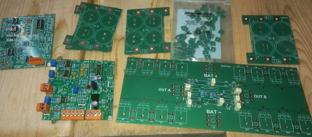 But i do seem to have an online shopping 'disability' in that I'm guaranteed to not notice I've missed something off the order until after I've gone through checkout  . I've got a 2nd order coming from lcsc and I've still got to source the fx1115 ferrite beads. . I've got a 2nd order coming from lcsc and I've still got to source the fx1115 ferrite beads.Also, ordering late at night, i fell for the sneaky aliexpress welding terminal trick and recieved a bag of M6 srews from china  . But then found that lcsc does the big terminals, albeit with M5 holes not M6. . But then found that lcsc does the big terminals, albeit with M5 holes not M6.Pete, Roger, i do have pvc electrical conduit, 20mm and 25mm in 3m lengths, so may try making a hoop from that, otherwise I'll be buying a hulahoop that resonates with me - all that overthinking! Curiously, when I'm working for someone else I'm much better at just getting on with it Anyway, couple more stupid questions:- Because i can't seem to think properly when ordering online, i ended up getting 74AC86 for U6, but then ordered U8 & U9 before realising i can just use 33R - i guess i just fit the resistors? There's no advantage in using U8 & U9 with the AC version of U6? And the other question is wether i should get some ally bar rather than mounting the mosfets direct to the heatsink? I seem to remember reading it would be a lot easier to fit the ferrite beads and base resistors in with ally bars, but are there other reasons that I've missed (otherwise, when i get the beads i may see if i think it's doable and do without the ally bar)? |
||||
| KeepIS Guru Joined: 13/10/2014 Location: AustraliaPosts: 2177 |
The aluminum bars make it easy to use wiseguys simple method of mounting the FETS instead of having to drill and tap 16 FET mounting holes. I've tapped 32 mounting holes in two heatsinks, but I'm going to use something similar to Wiseguys method for this next one. The FET beads are easier to mount with the correct FET to aluminum bar mounting position. The resistors and "8" of the ferrite beads are easy either way. The second 8 beads really need the aluminum bars. I use SN74AC86n and also mounted U8 and U9, I like the added high current source capability, and since I'm now driving two power boards, I'm happy that I did. FYI these beads are slightly smaller than others, but are used in some of the inverters that I have stripped down. Cost is amazing for the quantity, mine arrived quickly and are as advertised. Ferrite Beads EDIT: I used 3.5 X 3 X 1.5 but wiseguy originally used 5mm long beads, they have those as well in the listings. _ Edited 2024-08-07 10:30 by KeepIS NANO:Inverter V 8.2ks - Linux AvrDude GUI script V4.1 |
||||
| Murphy's friend Guru Joined: 04/10/2019 Location: AustraliaPosts: 678 |
Mab, a tip from somebody who has populated PCB's for half a century. Always fit the lowest height parts (resistors, diodes etc.) first, turn the board over and solder the legs. This way they get pushed flat against the board. Next do the IC sockets. And so on... I would solder tall parts like trimpots & connectors last for that reason. Also noticed you are using the more expensive IC sockets with the turned pins. Be very very careful when you insert the IC, it's rather too easy to fold one leg under (unobserved) as you press the IC on. Then you might spend lots of time working out why it's a no go board. This applies especially for the driver chips, mine had particularly thin fragile legs. Happy populating  |
||||
| mab1 Senior Member Joined: 10/02/2015 Location: United KingdomPosts: 282 |
Ok, then i guess I'll get some aluminium bar.  On the subject of ferrite beads: does it not reall matter then if i got some different ones? - as long as they're about the right size and ferrite? I can get the fx1115 i think, I'm just being a cheapskate and trying to find them with a supplier where i am ordering something else - which hasn't happened yet. This is probably the biggest pcb population I've done : i tend to do passives then heat sensitive, but then it's been a bit dependent on what I have here already, then the rest when it arrives. Actually i haven't soldered anything on the power board yet - i was just checking i had all the small bits before i submitted the order - but for the power board i was going to do the big terminals first as they'll get the board hot (though i could do the resistors 1st i suppose), then the little (SOT) transistors before the caps as the caps will be in the way if i do them 1st. Still waiting for the terminals to arrive... |
||||
| KeepIS Guru Joined: 13/10/2014 Location: AustraliaPosts: 2177 |
FYI, because of the size of the caps I used (quality parts from my parts bin) I mounted the IC sockets on the Power board PCB first, followed by Caps, small FETS, diodes and resistors in that order. When you get the IC sockets, dry fit them with the caps, this will give you a good idea of the very tight fitment with larger quality types similar to mine, very tight squeeze, but still simple to do. Yes, mount the big terminals first, and depending on what you use and heat applied, this will make it easier for any PCB cleanup of flux that may be required, especially on the component side of the PCB before the other small components have been mounted. _ Edited 2024-08-08 10:16 by KeepIS NANO:Inverter V 8.2ks - Linux AvrDude GUI script V4.1 |
||||
| rogerdw Guru Joined: 22/10/2019 Location: AustraliaPosts: 955 |
I suppose you could heat it and coax it into a hoop ... but for a couple dollars I'd just go buy the hula hoop. For all the work mine has done it still holds its shape well ... plus is only 18mm OD I do recall mine had a circumference of 2.2 metres ... so you could get longer loops in ... but I could always fit plenty for any of the windings I did. Yeah, now that you say that ... I'm the same there too. I'd probably have been better off working for a boss ... but I'm close on 39 years self employed. Too late to change now. Cheers, Roger |
||||
| Godoh Guru Joined: 26/09/2020 Location: AustraliaPosts: 664 |
Hi Roger, I get the hula hoop would be great for 48 volt transformers. The transformer I just finished needed 100 metres of 2.8mm diameter wire wound onto it (24 volt). It has been a very long time since I saw a hula hoop but I don't think that 50 turns of wire of that guage would fit on it. I have my transformer sitting on the bench now allowing the varnish to dry. Pete |
||||
| rogerdw Guru Joined: 22/10/2019 Location: AustraliaPosts: 955 |
Hi Pete, yeah I doubt you'd get 100 metres of 2.8mm into the hoop either. It depended what I was winding but I would fit just over 50 metres of 1.8mm ... though probably could have fitted 75 metres if really trying. But 2.8mm ... that's a whole different game. Still, how did all the Ozinverter guys get their windings done ... using little reels like old solder reels??? I can only assume they joined heaps of lengths together as they wound them. There's plenty of room around the outside to join the wire ... though for me it goes against the grain to join it at all if it can be avoided. So if I read you right, you've already wound yours ... what method did you use? And what were the specs for the toroid ... 100m at 2.8mm sounds like a lot of turns. Cheers, Roger |
||||
| Godoh Guru Joined: 26/09/2020 Location: AustraliaPosts: 664 |
HI Roger, the transformer I wound had the following specs. 170mm OD 100mm Id 145mm high It was three cores stacked vertically. I used 2.8mm diameter wire for the high voltage side and 12mm X 3.5mm flat glass insulated bar for the low voltage side. I had 224 turns on the high voltage winding and 12 turns on the low voltage side. I used a hoop made from a 25mm diameter piece of conduit. It started as a 4 metre length of conduit and I bent it into a fairly wild looking hoop. Cut a slot with a small angle grinder and wound the transformer with that. I taped over each layer of the high voltage winding with Terylene tape. Then over the high voltage winding again with Terylene tape. Dipped the whole transformer in varnish and it is air drying. Pete |
||||
| rogerdw Guru Joined: 22/10/2019 Location: AustraliaPosts: 955 |
Thanks for the explanation Pete, that makes sense. I can see a bigger diameter hoop and using bigger diameter tubing would make a big difference to the "capacity" of the hoop ... so Mab1 if you haven't started yet ... maybe work out what lengths you need for your windings and maybe using some of your conduit may be an easier option. I was also feeling a bit disappointed that I didn't dip my transformers in varnish because there was a bit of a rattle from one or two of them ... but since adding the AC-coupled grid tie inverter ... that makes the whole thing rattle and rumble and warble and chirp all the time that there's any solar dc on the input. When the final watt of power disappears on dark ... the Warpverter suddenly becomes quiet again and sounds really good. Lucky the thing is out in the shed and noise is not an issue. Cheers, Roger |
||||
| mab1 Senior Member Joined: 10/02/2015 Location: United KingdomPosts: 282 |
ok, so i ought to work out how much wire I'll need (and work out/measure how long my salvaged wires are), then see what capacity hoop I'll need. Another possibility could be alkathene (mdpe) water pipe which comes in rolls so naturally forms a hoop - i have some offcuts of 25mm dia that might be better than trying to make an even hoop from conduit. Cheers Marcus |
||||
| Cpoc Senior Member Joined: 28/05/2024 Location: PortugalPosts: 109 |
Hey Godoh 2.8mm and 224 turns ouch that must have hurt your hands. Mine is only 104 turns with 2.9mm wire. The secondary winding is the worst part of the transformer build. I can build 2 transformers with the same effort that you put into building one. My core is wider but shorter in height. My cross section is 7000 mm2. |
||||
| Godoh Guru Joined: 26/09/2020 Location: AustraliaPosts: 664 |
Hi Cpoc, it didn't hurt my hands, I just put one layer on each day (about 60 turns per layer) then taped over that layer, then the next day put the next layer and tape on. I used a wooden hammer handle to compress the inside of the windings to the core and just took my time. My core is about 50 cm2. I just used cores that i had, 2 old powerjack cores and another core that I got second hand. I had to take some of the metal out of the centre of one core and put it on the outside to make them all the same size and also to get a 100mm centre hole. My other inverter transformer only had a 90mm hole and that was a very tight squeeze to get the low voltage winding in. Cheers Pete |
||||
| Cpoc Senior Member Joined: 28/05/2024 Location: PortugalPosts: 109 |
Thanks for the tip. I never thought of using a wooden hammer. As for me I cannot source any used core here so I order custom made one from the UK. So you build your cores slow and steady…..nice. |
||||
| Gizmo Admin Group Joined: 05/06/2004 Location: AustraliaPosts: 5182 |
I picked up a free Sunny Boy grid tie inverter a few weeks ago. I had converted one of these into a inverter a few years ago using the old Powerjack(?) boards. When I tore this one down, I see unfortunately it looks like they started potting their transforms at some point. 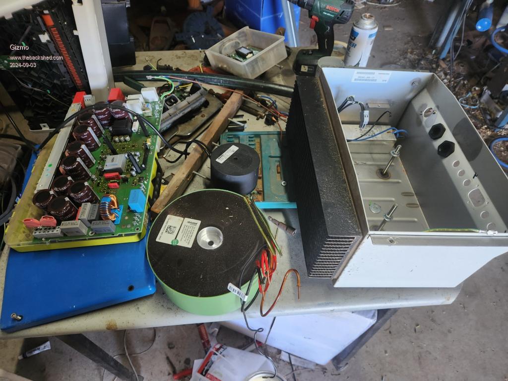 Anyone had any luck de-potting these? Or should I just hack into it to get the iron core and put the copper in the scrap steel bin? Glenn The best time to plant a tree was twenty years ago, the second best time is right now. JAQ |
||||
| The Back Shed's forum code is written, and hosted, in Australia. | © JAQ Software 2026 |
