
|
|
Forum Index : Microcontroller and PC projects : RPZ Compute module
| Author | Message | ||||
| Mixtel90 Guru Joined: 05/10/2019 Location: United KingdomPosts: 8913 |
Definitely not intended to do it. :) It's a totally different concept. I've no Click modules and have no experience of them, but I know that they are designed as IO modules. As designed RPZ compute modules are too small to accept even a small Click module. They are also "intelligent" in their own right and are capable of operating independently, only getting occasional commands from the master controller. I designed a board for Click some time ago but I've no idea if it works. I couldn't test it. :) I'd suggest that if you want Mikrobus then the best way is to use a Mikrobus system, not attempt to shoehorn it into something else. 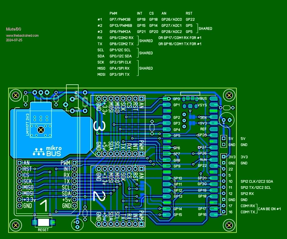 Edited 2024-07-25 22:55 by Mixtel90 Mick Zilog Inside! nascom.info for Nascom & Gemini Preliminary MMBasic docs & my PCB designs |
||||
| zeitfest Guru Joined: 31/07/2019 Location: AustraliaPosts: 683 |
I was thinking more of the zero / rpz boards morphed onto a click module. So they could then plug into a mikrobus bus and use it and the range of accessories. [ assuming the range is still available ! haven't seen much of them.]. Just an idea. ATM I am looking for pico type boards with power, sd card sockets and I2C i/o. The rpz looks interesting too, I am going to look at the pinouts. |
||||
| Mixtel90 Guru Joined: 05/10/2019 Location: United KingdomPosts: 8913 |
I'm working on a manual for the RPZ system at the moment. There'll be quite a bit of info in it about how it works and how it's intended to be used. Mick Zilog Inside! nascom.info for Nascom & Gemini Preliminary MMBasic docs & my PCB designs |
||||
| Mixtel90 Guru Joined: 05/10/2019 Location: United KingdomPosts: 8913 |
Something like this? The problem is that each Click module is a slave. They are selected by the CS pin, I think. Putting a Zero onto a Click module gives you something that could probably control one other Click module, but maybe not two as to comply with the Click spec it only has one CS pin. However, if you chose the modules correctly one could be on SPI (as a slave) and the other on the COM port with the COM one continuously active. It probably limits what you can do with it.  Further comment added: I suppose, if pullup resistors were added, this could be used to control Click modules that hang only on the I2C bus, if such things exist. This stuff is pretty much outside my field, as I said. . Edited 2024-07-26 18:05 by Mixtel90 Mick Zilog Inside! nascom.info for Nascom & Gemini Preliminary MMBasic docs & my PCB designs |
||||
| zeitfest Guru Joined: 31/07/2019 Location: AustraliaPosts: 683 |
yes I think so, the I2C bus would connect a number of modules. Probably not much distinct benefit or point though. |
||||
| zeitfest Guru Joined: 31/07/2019 Location: AustraliaPosts: 683 |
yes I think so, the I2C bus would connect a number of modules. On thinking more about it, probably not much distinct benefit or point though. Edited 2024-07-26 22:27 by zeitfest |
||||
| zeitfest Guru Joined: 31/07/2019 Location: AustraliaPosts: 683 |
Looking at the standard RPZ - I think they could be paralleled in bulk ? Say with the right-angle connector as in the module, with the power and I2C pins in common connections, maybe 16 or so ... I am going to get a zero now  PS what is the size in mm ? Edited 2024-07-27 10:24 by zeitfest |
||||
| Mixtel90 Guru Joined: 05/10/2019 Location: United KingdomPosts: 8913 |
Paralleled in bulk? Do you mean like the motherboard on the first page of this thread? They were always designed to do this. They will pack closer if you rearrange the IO tracks & connectors, but remember that some have a module plugged onto the front and some have it plugged onto the back. You *could* similarly parallel the bare RP2040-Zero, but it would be difficult, using three PCBs if you ever wanted to make the stack repairable. :) Mick Zilog Inside! nascom.info for Nascom & Gemini Preliminary MMBasic docs & my PCB designs |
||||
| zeitfest Guru Joined: 31/07/2019 Location: AustraliaPosts: 683 |
Doh ! My mistake [I thought it was limited to two or so ] Your excellent idea has taken off |
||||
| Mixtel90 Guru Joined: 05/10/2019 Location: United KingdomPosts: 8913 |
This is the manual so far. I think it's mostly right but not all the illustrations are correct. That doesn't really matter. RPZ Compute Sytem Manual.pdf I've been tweaking a couple of modules' I'll hopefully be posting gerbers for two 100mm x 100mm boards very soon. The isolated COM module (the MIDI one) will be missing because it won't fit. That may have to wait until I think of something else to plug into the system. At the moment I'm intending to eventually post the SL6 file that includes everything, but no schematics as they are so trivial to sketch out from the PCBs if you really need them. Mick Zilog Inside! nascom.info for Nascom & Gemini Preliminary MMBasic docs & my PCB designs |
||||
| lizby Guru Joined: 17/05/2016 Location: United StatesPosts: 3788 |
Did you ever publish gerbers for this? 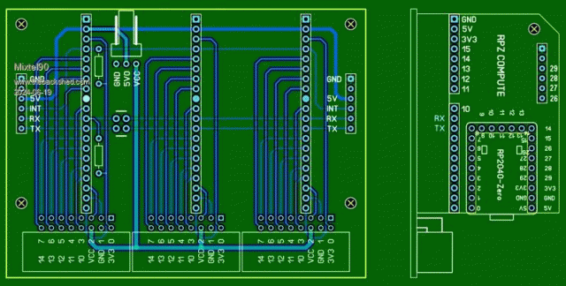 Actually, I'm only interested in the 3x part--I already have the RPZ board in quantity. PicoMite, Armmite F4, SensorKits, MMBasic Hardware, Games, etc. on FOTS |
||||
| Mixtel90 Guru Joined: 05/10/2019 Location: United KingdomPosts: 8913 |
I'm not sure... I think it got tweaked. I'll sort it out. :) Mick Zilog Inside! nascom.info for Nascom & Gemini Preliminary MMBasic docs & my PCB designs |
||||
| Mixtel90 Guru Joined: 05/10/2019 Location: United KingdomPosts: 8913 |
I've just had a look and it did get tweaked. :) The 100x100 board includes the RPZ Compute and the isolated serial port (described as a tool in the manual). I can change the Compute for something else if you like and/or I think I could swap the isolated port for the indicator module. The Compute module has changed slightly since the first version. It just allows a couple more options, that's all (I think!). Mick Zilog Inside! nascom.info for Nascom & Gemini Preliminary MMBasic docs & my PCB designs |
||||
| lizby Guru Joined: 17/05/2016 Location: United StatesPosts: 3788 |
I can't tell which of the PCBs linked from your signature that would be. PicoMite, Armmite F4, SensorKits, MMBasic Hardware, Games, etc. on FOTS |
||||
| Mixtel90 Guru Joined: 05/10/2019 Location: United KingdomPosts: 8913 |
Have a look at the manual that I posted on 27 July. It doesn't show the PCBs for the indicator and isolated links, but it describes them. It also describes the rest of the boards. I've not done a proper update to the boards in my sig for a while. It's time I did. :) . Edited 2024-08-09 22:40 by Mixtel90 Mick Zilog Inside! nascom.info for Nascom & Gemini Preliminary MMBasic docs & my PCB designs |
||||
| lizby Guru Joined: 17/05/2016 Location: United StatesPosts: 3788 |
Yes, I had downloaded that manual. It has no mention of gerbers. Have you published the gerbers? PicoMite, Armmite F4, SensorKits, MMBasic Hardware, Games, etc. on FOTS |
||||
| Mixtel90 Guru Joined: 05/10/2019 Location: United KingdomPosts: 8913 |
No. I'll sor them ou for you. However, would you like me to change the 100x100 board since you already have the Compute modules? I can include any of the others plus either of the tools mentioned in the manual. I could do you gerbers just for the backplane but it seems a waste if you can cut more boards from it for the same price. :) Mick Zilog Inside! nascom.info for Nascom & Gemini Preliminary MMBasic docs & my PCB designs |
||||
| lizby Guru Joined: 17/05/2016 Location: United StatesPosts: 3788 |
If I'm reading the manual correctly, there are 5 modules in addition to the RPZ. Depending on what will fit, I'd prioritize: RPZ COMPUTE ESP, RPZ COMPUTE BT, RPZ COMPUTE VGA, RPZ COMPUTE Y40, RPZ ISOLATED COM But if all 5 would fit on a separate board, I'd order that (and then maybe you could add a 4th slot on the bus). But I don't want to put you out. I appreciate all the effort you put into these designs. PicoMite, Armmite F4, SensorKits, MMBasic Hardware, Games, etc. on FOTS |
||||
| Mixtel90 Guru Joined: 05/10/2019 Location: United KingdomPosts: 8913 |
I can only get 4 modules plus the indicator tool onto a 100x100 board. Another 100x100 will take a 3-slot motherboard, one module and either of the tools. So, at the moment I can't manage all six modules if I keep to 100x100 boards, unfortunately. :) The number of motherboard slots was decided by the width of the 16-pin IDE connectors originally. I think squeezing four modules to a motherboard might be a bit tight, even with some sort of smaller connectors. However, it's easy to link two or more motherboards together, and you have to buy five anyway. :). Mick Zilog Inside! nascom.info for Nascom & Gemini Preliminary MMBasic docs & my PCB designs |
||||
| Mixtel90 Guru Joined: 05/10/2019 Location: United KingdomPosts: 8913 |
RPZboard1.zip RPZboard2.zip Board1: MB1 ISOLATED COM ISOLATED TERMINAL Board2: ESP BT JDY-40 VGA Monitor I've left the Compute module off so that you get the set. :) I've started on one for the nRF24L01 and one for a general purpose SPI, which would drive a LCD but without Touch. Not sure when they'll be ready though. ========================== This replaces Board1 for those who don't have the Compute module. It doesn't have the ISOLATED COM module on it. MB1+Compute.zip Edited 2024-08-10 03:45 by Mixtel90 Mick Zilog Inside! nascom.info for Nascom & Gemini Preliminary MMBasic docs & my PCB designs |
||||
| The Back Shed's forum code is written, and hosted, in Australia. | © JAQ Software 2026 |
