|

|
Forum Index : Microcontroller and PC projects : PM: VGA USB version - no VGA....
| Author | Message | ||||
| lizby Guru Joined: 17/05/2016 Location: United StatesPosts: 3150 |
This is the same symptom I had for one of my 5 boards--the other 4 tested OK for everything I tried--console through USB_C with TeraTerm (didn't need to set baud rate because I'd previously had PicoMites given the same COM port which were set at 115200), VGA, SD, keyboard--haven't tried audio (should headphones work?). For the faulty board, per BigMik's and Peter's suggestions, I found that R31 was 2k8 instead of 5k1 (I tested a working board and it was 5k1). I don't know if this might be your problem (or even if it actually is the cause of my fault), but it might be something worth testing. Do all of your PCBs fail to present console on the USB_C? I flashed using the USB_A to USB_A port, and then removed that and plugged in the USB_C cable. If the pico was previously flashed with a prior version of the firmware, did you try erasing it? PicoMite, Armmite F4, SensorKits, MMBasic Hardware, Games, etc. on fruitoftheshed |
||||
| Turbo46 Guru Joined: 24/12/2017 Location: AustraliaPosts: 1611 |
It may be OK for a short test but I wouldn't risk it. It may not even prove anything if you have two outputs fighting each other the stronger one will win and you may not get feedback anyway. It is a pity if JLC are allowing their standards to slip or maybe some resistors were mixed. People have been known to have a whoopsie with their SMD resistors.  Bill Keep safe. Live long and prosper. |
||||
Grogster Admin Group Joined: 31/12/2012 Location: New ZealandPosts: 9306 |
@ Bill: Yeah, that was what I was thinking also. I won't short out the pins - I don't want to make matters worse!  I've tested a 2nd board, and it won't talk to me either.  Programs fine using the USB A-A in the usual way, LED1 is blinking away happily, so I know the FW must actually be running, but not a sausage out of the USB-C connector. I noted in the other thread(the main one announcing this new board), that someone tried an EXTERNAL USB-TTL converter on GP8 and GP9, so I plan to try that next. And I will check the value of those resistors and report back. Could the wrong values there actually cause this issue, though, that is the question. Mick(the big one) mentioned he has had issues with the CH340 chip in the past, and so have I on other boards(not MMBASIC boards), so personally - and with some amount of bias probably - I think the fault is there. An external USB-TTL converter on GP8 and GP9 will prove weather the 2040 PM console is actually alive or not. I love a good mystery.  I'll update this thread when I have had a bit more of a tinker. Smoke makes things work. When the smoke gets out, it stops! |
||||
| robert.rozee Guru Joined: 31/12/2012 Location: New ZealandPosts: 2350 |
hi Grogster, you could try plugging into a USB2 port on your PC. those resistors around the USB-C socket are, i believe, for ID purposes; if plugged into a USB2 port at the PC end they are ignored. cheers, rob :-) addendum: to clarify, a USB2 port as opposed to a USB3 port. used to be that there was a colour difference (blue vs black) but that seems to have been abandoned these days. Edited 2024-03-03 14:50 by robert.rozee |
||||
Grogster Admin Group Joined: 31/12/2012 Location: New ZealandPosts: 9306 |
Thanks, Rob, I will try that and post back with results. Smoke makes things work. When the smoke gets out, it stops! |
||||
| matherp Guru Joined: 11/12/2012 Location: United KingdomPosts: 9115 |
Grogster - what firmware are you programming? You should be using PicoMiteVGAUSBV5.09.00b5 If you have programmed the normal PicoMiteVGA then the console will be on the USB-A port and the CH340 won't do anything useful unless used as a standard com port UPDATE Just re-read the thread. If you can set the baudrate then the CH340 is connecting so there is no H/W problem with the ch340/USB-C. So IFF you have the correct firmware then you need to look at the connection between the CH340 and the RP2040 Edited 2024-03-03 18:39 by matherp |
||||
| Mixtel90 Guru Joined: 05/10/2019 Location: United KingdomPosts: 6787 |
You could try a 1K resistor between the CH340 RXD and TXD (not sure of the numbers offhand). That wouldn't cause any damage. I don't think they can ever both be outputs anyway unless the chip is faulty (just looking at the datasheet). I've shorted them on the little USB-TTL modules to test them anyway. Nothing exploded. :) Mick Zilog Inside! nascom.info for Nascom & Gemini Preliminary MMBasic docs & my PCB designs |
||||
| phil99 Guru Joined: 11/02/2018 Location: AustraliaPosts: 2135 |
Are there series resistors between the CH340 and the RP2040 like on Adduinos? If not linking Tx and Rx wont work as the RP2040 Tx pin will be holding the CH340 Rx pin high. |
||||
| lizby Guru Joined: 17/05/2016 Location: United StatesPosts: 3150 |
I good thought. I have trouble locating a USB2 port. I plugged a USB hub into the laptop, and plugged the PicoVGAUSB board into that. I didn't get the "unrecognized USB device" message, but also didn't get a COM port. The heartbeat LED is flashing. PicoMite, Armmite F4, SensorKits, MMBasic Hardware, Games, etc. on fruitoftheshed |
||||
| Mixtel90 Guru Joined: 05/10/2019 Location: United KingdomPosts: 6787 |
The CH340C USB series resistors are R36 and R37. They should be 27R. Mick Zilog Inside! nascom.info for Nascom & Gemini Preliminary MMBasic docs & my PCB designs |
||||
| matherp Guru Joined: 11/12/2012 Location: United KingdomPosts: 9115 |
They are on the USB side - that appears to be working. My bet is still on firmware VGA vs VGAUSB |
||||
| Mixtel90 Guru Joined: 05/10/2019 Location: United KingdomPosts: 6787 |
Grogster: Clutching at straws here. If you are using a "posh" USB-C cable then try a cheap one. It appears that some "posh" cables include a "Emarker" ROM that is connected to the CC pins and could be causing a problem. In theory one of the CC pins should be grounded and used for sensing, the other should provide the chip with power. Linky Above all, as Peter says, make sure you have loaded the USB VGA version of the firmware. The ordinary VGA version is no use on this board. Edited 2024-03-04 05:46 by Mixtel90 Mick Zilog Inside! nascom.info for Nascom & Gemini Preliminary MMBasic docs & my PCB designs |
||||
TassyJim Guru Joined: 07/08/2011 Location: AustraliaPosts: 6098 |
Is it plausable to load the standard picomite firmware and then test the CH340 side using Basic and a CRO and terminal program? Connecting both the USB ports to the same PC hub should be OK because their 5Vs are common. If concerned, a USB cable with the 5V snipped... Jim Edited 2024-03-04 06:22 by TassyJim VK7JH MMedit MMBasic Help |
||||
| Mixtel90 Guru Joined: 05/10/2019 Location: United KingdomPosts: 6787 |
Possibly. If you: disable the keyboard and enable a serial terminal on the USB converter pins. You can't have a VGA display unless the version of MMBasic supports OPTION VGA PINS, of course. Another way would be to connect a logic analyser to the TXD and RXD lines. We know the version of firmware that definitely works on this board so the first step is to ensure that that's what's loaded. 5.09.00b0 is what's on mine, but I see Peter recommends b5. I haven't tried that. Someone asked if you could test the audio with headphones. Yes, you can, on the line out jack, but I'd recommend a) don't use 8R impedance and b) it's LOUD and the volume control is only for the speakers (use PLAY VOLUME). You can't use headphones on the speaker terminals as the system stands. Sound quality is better on the speakers using the proper volume control. Mick Zilog Inside! nascom.info for Nascom & Gemini Preliminary MMBasic docs & my PCB designs |
||||
Grogster Admin Group Joined: 31/12/2012 Location: New ZealandPosts: 9306 |
Can someone please link me to the most recent version of the FW for this board. I downloaded the version from Geoff's website, but it is listed as version 5.08.00, which I note is still an older version then that which Peter mentions above. I still think at this point, that I am using the wrong FW. I'll have a look through the original thread too - Peter may have posted links there. EDIT: I found it on this thread. I will flash that in, and see if we have talkie!  Edited 2024-03-04 07:49 by Grogster Smoke makes things work. When the smoke gets out, it stops! |
||||
Grogster Admin Group Joined: 31/12/2012 Location: New ZealandPosts: 9306 |
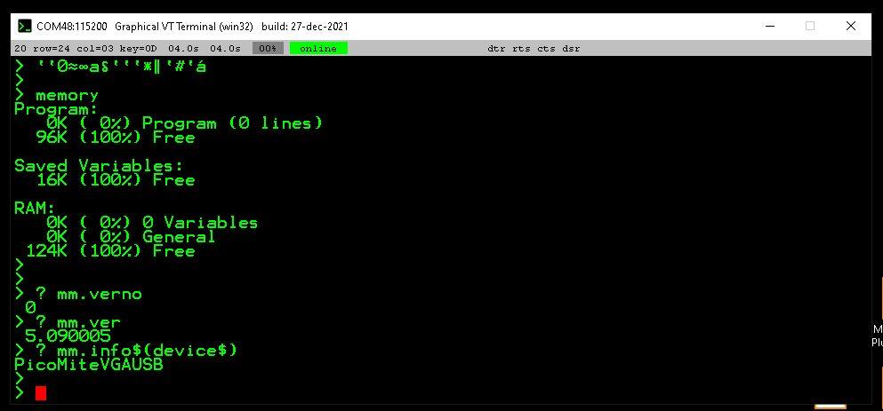
WORKING! - YAY!!!!!  I noted that LED1 blinks once quickly, then settles into the usual heartbeat blink. Is that by design, so you know it is the VGAUSB version of the FW? I expect it probably is, and is a good way to know that you have that version "Inside". RIGHT! Now to set the options as on the rear of the board, in the order stated, and then I can do some more tinkering.  Thanks for everyone's help and posts - they were useful, and encouraged me to not give up and move onto something else, cos I have a rather large "To-do pile" right at the moment! Smoke makes things work. When the smoke gets out, it stops! |
||||
| stanleyella Guru Joined: 25/06/2022 Location: United KingdomPosts: 2129 |
I'm glad you sorted it. no more ps2, get a mini wireless kb. I never had problems with usb vga until 00b3 and 00b4. option reset and 00b5 was ok, dunno why.. but I use veroboard  |
||||
Grogster Admin Group Joined: 31/12/2012 Location: New ZealandPosts: 9306 |
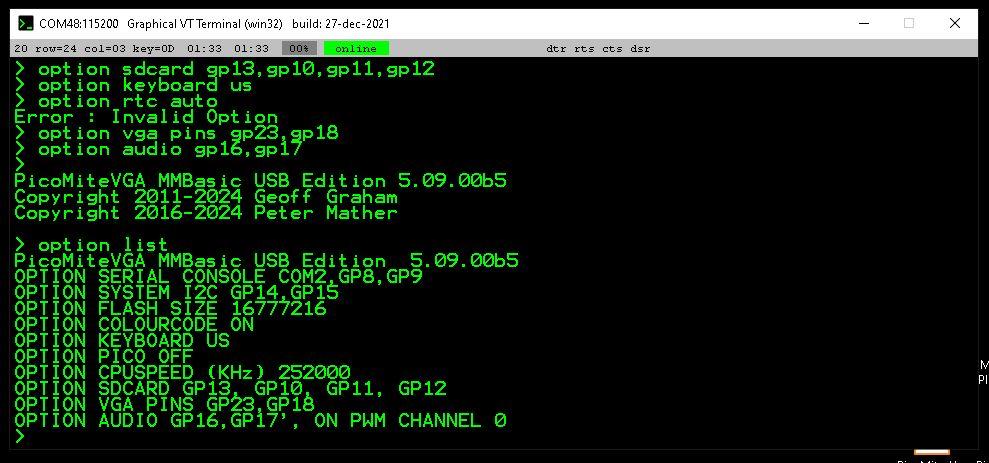
OPTION RTC AUTO throws an error: (invalid option)  This may not have been added to the beta yet - yes/no? Smoke makes things work. When the smoke gets out, it stops! |
||||
| disco4now Guru Joined: 18/12/2014 Location: AustraliaPosts: 896 |
Looking at the manual it might need ENABLE or DISABLE as well. Looking at the code it will say "Invalid Option" if one is not specified. Try OPTION RTC AUTO ENABLE or OPTION RTC AUTO DISABLE Latest F4 Latest H7 |
||||
| matherp Guru Joined: 11/12/2012 Location: United KingdomPosts: 9115 |
Its an omission on the silkscreen. As disco4now says add "enable". Corrected on the latest gerbers |
||||