
|

|
Forum Index : Microcontroller and PC projects : PicoMite VGA - USB to PS2 Keyboard Adapter
| Author | Message | ||||
| stanleyella Guru Joined: 25/06/2022 Location: United KingdomPosts: 2129 |
I never tried the 2 picomite usb kb version. can't get into github. I thought the usb betas were the latest. my tests work fine for kb even wireless. |
||||
| Turbo46 Guru Joined: 24/12/2017 Location: AustraliaPosts: 1611 |
Never mind Leo, I've found it.  Going by what Mick and Peter has said. You could short out the diode D! but because it will protect against a reversed input power supply and only drop the supply voltage by 0.3 or 0.4 volts I would leave it unshorted for now. You can put a short across it when the thing is proven to work if you want to. Pin 40 is unconnected but 5v is connected to pin 39. It seems to me that all you need to do is put a link between pins 39 and 40. PLEASE DO NOT DO THIS WITHOUT MICK'S BLESSING! Mick knows this stuff inside and out and he will know if it is correct or not. Bill Keep safe. Live long and prosper. |
||||
| LeoNicolas Guru Joined: 07/10/2020 Location: CanadaPosts: 479 |
I have the PicoMite VGA v2.0 I bought from Volhout. The board says "Designed by Mixtel90". It's a beautiful board  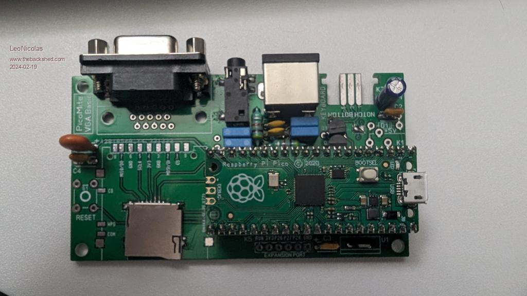 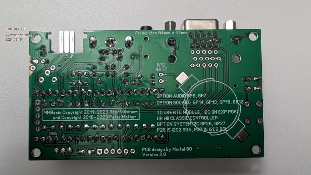 |
||||
| LeoNicolas Guru Joined: 07/10/2020 Location: CanadaPosts: 479 |
Ok, I will wait for Mick's blessing  |
||||
| Turbo46 Guru Joined: 24/12/2017 Location: AustraliaPosts: 1611 |
Please note if the above is acceptable then: This means that, if you plug the Pico into a PC to program new firmware while it is being powered externally via a plug pack you WILL RISK DAMAGE TO THE USB PORT IN THE PC because you will be connecting the two 5v power supplies together. If the diode D1 is still in circuit then the plug pack will be OK - the diode will prevent back feeding. To program new firmware the external power supply MUST be disconnected. Bill Keep safe. Live long and prosper. |
||||
| robert.rozee Guru Joined: 31/12/2012 Location: New ZealandPosts: 2350 |
hi LeoNicolas, get yourself one of these: https://www.ebay.com/itm/373704840745 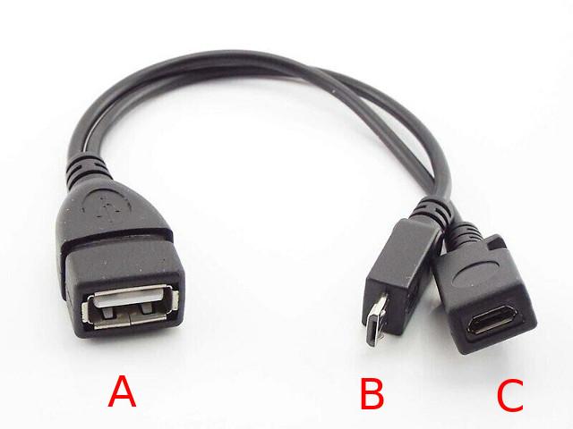 -> plug your keyboard into the USB A socket (A); -> plug the micro USB plug (B) into the pico; -> connect your 5v power to the micro USB socket (C) - you can get this from a phone charger or (see below) from a USB port on your computer. to upgrade the pico's firmware, unplug the micro USB plug (B) from the pico and connect the pico to your PC (while holding down the BOOTSEL button) using a regular micro USB to USB A cable. the above Y cable may or may not pass through DM and DP lines to the micro USB socket (C). in theory they should not be. if you can not check this and are concerned (worst case, the keyboard will not respond), you can just cut off the micro USB socket (C) and replace it with a barrel jack or similar. Peter: is there any way that TinyUSB can tell the difference between a host and a device connection, and if it sees a host (ie, PC) jump immediately to the bootloader? this would (maybe?) remove the need for users to press BOOTSEL on the picomite USBs. cheers, rob :-) Edited 2024-02-19 12:59 by robert.rozee |
||||
| Turbo46 Guru Joined: 24/12/2017 Location: AustraliaPosts: 1611 |
Good find Rob, If I am correct that would mean no modifications to the board are needed. Also, if I am correct, you should unplug the external power supply before connecting the Pico to the PC to avoid damage that could result from connecting the two power supplies together. Having said that, I prefer the mod linking pins 39 and 40. Just a bit neater. Again Leo, Please wait for Mick's blessing. Not that I expect you to have one of those cables to hand?  Bill Keep safe. Live long and prosper. |
||||
| LeoNicolas Guru Joined: 07/10/2020 Location: CanadaPosts: 479 |
javavi I tried your solution, and it didn't work. I downloaded from Github, built, and uploaded to the RP2040 the hid2cdc. It can recognize the keyboard, as shown in the screenshot below (from the GPIO 0), but there is no sign of life in the PicoMite VGA... nothing is printed on the screen. I don't have an oscilloscope to check the PS2 signals. 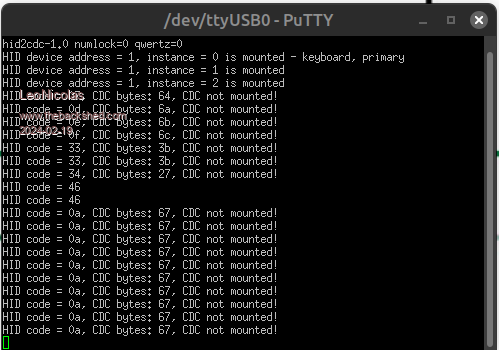 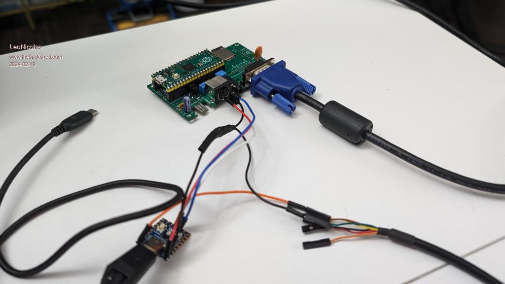 Edited 2024-02-19 16:04 by LeoNicolas |
||||
| Volhout Guru Joined: 05/03/2018 Location: NetherlandsPosts: 4233 |
Hi Leo, You may have the wrong firmware. You should use ps2x2pico In combination with the normal (Geoff's site) V5.08.00 PicoMiteVGA firmware. AFAIK the hid2cdc is related to following thread hid2cdc Were you use a separate pico (i.e. a ZERO) as a "dummy pc" to route the USB keyboard signals to the PicoMite CDC port. The ZERO pico is mimicking a terminal program (only the input section), similar as if you where typing onyour laptop or PC keyboard in a terminal program (i.e. putty). The hardware setup in your photo uses the ZERO pico to translate USB keyboard to PS2 keyboard. A different application. If I where to guess (just based on the name) you should have a hid2ps2 program in the pico ZERO. Check with Javavi... Oh, when you are new to this development, I may have to summarize: 1/ There is the option of USB to PS2 translation (your wiring), works with standard PicoMiteVGA firmware 5.08.00 or newer. 2/ There is the option hid2cdc, works with a standard PicoMiteVGA 5.08.00 or newer. 3/ There is the option "USBpicomite", where Peter has created special software to make the pico accept a USB keyboard. Requires special firmware USBPicoMite 5.09.00beta's, and special hardware (UART-USB cable for connection to PC if you use an IDE like MMEdit). The new "CMM1.5-or-something" thread is the development of such hardware. Volhout Edited 2024-02-19 17:36 by Volhout PicomiteVGA PETSCII ROBOTS |
||||
| Mixtel90 Guru Joined: 05/10/2019 Location: United KingdomPosts: 6787 |
To convert a PicoMite VGA Basic board to USB ============================================ You will need: The latest version of the VGA USB firmware. Note, that no other versions are suitable. A USB to TTL adapter. I prefer USB-C, but use whatever you like. A microUSB plug to USB-A female socket adapter Optional - a small unpowered USB hub A USB keyboard - you can't use the PS2 keyboard with the USB firmware. You have three 5V supply options: The 5V Barrel jack socket The USB-TTL adapter The microUSB socket on the PicoMite The important thing is that you must only ever have one source of supply connected at any time. The microUSB socket will only ever power the system during firmware updating. The USB-TTL adapter supply will usually only be used if console access is required, but it can be used anytime. Powering via the barrel jack obviously doesn't provide console access so is of limited use. Link pins 39 and 40 (MBUS and VSYS) on the PicoMite socket. This enables the 5V output to the USB system. The USB-TTL adapter should be connected as follows: GND - GND 5V - PicoMite 5V rail (unless the barrel jack supply will be the normal one) RXD - GP8 TXD - GP9 No other connections are required. The USB-TTL adapter will be used as the console connection and is a serial port running at 115200 baud by default. The micro USB socket on the PicoMite becomes the USB port and is run in Host mode. It supplies 5V to the keyboard and/or USB hub so is now not suitable for connection to a PC unless the USB-TTL adapter is unplugged. Possible problems: If you see long strings of characters on the console when you power up or reset the board then the baud rate is wrong. It should be set to 115200 by default. When using a USB-TTL adapter the baud rate isn't set automatically. If the console refuses to work you may have to isolate GP8 and GP9 from the PS2 level shifter circuitry. This can be done by cutting the two traces on the top of the board underneath the PicoMite. I've not tested this but I suspect it may not cause a problem. If you have problems with the USB port add two 15K resistors from D+ and D- to ground. This can be neatly done underneath the PicoMite. Once the USB firmware has been installed any updates must be done by disconnecting the USB-TTL adapter and the USB hub, allowing a programming connection to the microUSB socket on the PicoMite. The normal hold Boot and power up system can then be used. Mick Zilog Inside! nascom.info for Nascom & Gemini Preliminary MMBasic docs & my PCB designs |
||||
| robert.rozee Guru Joined: 31/12/2012 Location: New ZealandPosts: 2350 |
you are correct  no modifications should be required to the PCB holding the pico. no modifications should be required to the PCB holding the pico.when you unplug the micro USB plug (B) from the pico, power that was being fed in at (C) will no longer be reaching the pico. so no  you do not need to unplug anything else if power is coming via the Y cable. you do not need to unplug anything else if power is coming via the Y cable.i see others have suggested using a USB to serial bridge attached to pins GP8 and GP9 of the pico, and then using the 5v line from that bridge to power the pico. using the USB to serial bridge to power a picomite VGA is not a very good idea. you can not rely upon being able to draw more than 100mA from a PC's USB port via a bridge, and pico + VGA + SD + USB keyboard could easily exceed this 100mA limit. it is by far safer / more reliable to power your picomite VGA + USB keyboard from a phone charger that has a micro USB plug on the end of its lead. cheers, rob :-) |
||||
| Mixtel90 Guru Joined: 05/10/2019 Location: United KingdomPosts: 6787 |
Nowadays, apart from the occasional laptop, it's unusual to find a PC that can't provide enough current for a PicoMite VGA. USB *chargers* on the other hand can be very unreliable. A PC USB port is intended to power devices., it's not intended for charging. Consequently the available current, even for a USB2 socket, is usually about 500mA for USB1 and USB2, 900mA for USB3. Sometimes this current is shared across all the USB ports. Some PCs simply protect the USB supply with a polyswitch. The little fanless PC that I'm using has no problem powering a CMM2 or PicoMite with fully backlit SSD1963. Chargers *should* negotiate and provide the current requested by the device. If there is no negotiating then the available current is decided by resistors biasing the D+ and D- lines. A common method that has become almost standard is to short them together in the charger (sometimes with high value centering resistors), indicating to the device that maximum charging current is available. USB-C can also negotiate the voltage. A PC won't usually do this, it will normally stick to 5V but some chargers can increase the voltage for fast charging. This can be a minefield as the necessary electronics to provide a higher voltage can be in the USB-C lead itself. Edited 2024-02-19 22:58 by Mixtel90 Mick Zilog Inside! nascom.info for Nascom & Gemini Preliminary MMBasic docs & my PCB designs |
||||
| robert.rozee Guru Joined: 31/12/2012 Location: New ZealandPosts: 2350 |
that may well be the case in the northern hemisphere. but here in the southern hemisphere our PCs regularly comply with the USB specifications and limit available current accordingly. and our USB chargers are reliable. perhaps it is because of the warmer weather, or our electrons spinning in the opposite direction? cheers, rob :-) |
||||
| Mixtel90 Guru Joined: 05/10/2019 Location: United KingdomPosts: 6787 |
You never know. :) Mick Zilog Inside! nascom.info for Nascom & Gemini Preliminary MMBasic docs & my PCB designs |
||||
| stanleyella Guru Joined: 25/06/2022 Location: United KingdomPosts: 2129 |
New wireless kb arrived. £5.75. Works. Checking asc(inkey$) and the keypad. pc rear usb more current than front panel usb. |
||||
| LeoNicolas Guru Joined: 07/10/2020 Location: CanadaPosts: 479 |
Hello everyone Good news, it worked  The trick was to replace the RP2040 firmware with ps2x2pico. I was misled by the text "PicoMiteVGA variant" on the ps2x2pico README page. The final configuration is precisely as shared by javavi. The 5v outputted by the PS2 connector is powering the RS2040 board and also the keyboard. The power source is connected to the PicoMite Raspberry board via micro USB. I don't think a level shifter is necessary. The RP2040 is powered by the 5v line coming from the PS2 connector, and the Pico is already expecting 5v signals coming from the same PS2 connector. A special thank you to javavi, stanleyella, Mixtel90, Volhout and Turbo46 Now I need to answer another question: Will Knightmare run on a PicoMite?  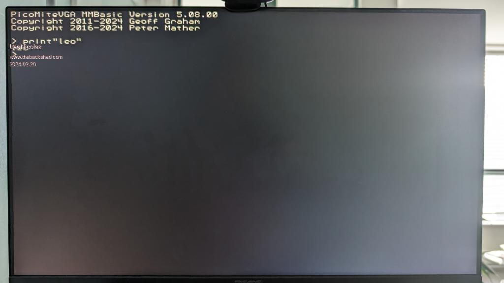 Edited 2024-02-20 03:40 by LeoNicolas |
||||
| stanleyella Guru Joined: 25/06/2022 Location: United KingdomPosts: 2129 |
Leo sir,good day. was the original 2 picomite to get usb keyboard your idea? I used the Matherp idea of usb to ttl for console and usb socket as kb. I have only tried Peters usb version but seems sound solution. the usb wireless keyboards have mouse pad so want me to test? |
||||
| LeoNicolas Guru Joined: 07/10/2020 Location: CanadaPosts: 479 |
My original idea was to use a USB keyboard on the PicoMite VGA. I don't have space for a second keyboard that only supports PS2. Peter's USB version looks clean, but I avoided it because I feared frying my board. For his solution, I need to power the Pico using a method other than the traditional USB connector, which will be used to connect the keyboard. I'm not testing the mouse. I aim to run Knightmare on the PicoMite and use it as a platform for other future games. Maybe one day we can use the mouse on a game like Monkey Island implemented in MMBasic  |
||||
| stanleyella Guru Joined: 25/06/2022 Location: United KingdomPosts: 2129 |
Leo sir, your idea for usb was brill imho. the idea of picomite for a usb to ttl seemed a waste. Matherps implementation seems more sensible and works. I use the usb to ttl converter as 5V connected to VBUS, powers lcd backlight. dunno your picomite circuit |
||||
| LeoNicolas Guru Joined: 07/10/2020 Location: CanadaPosts: 479 |
javavi needs to take credit for the solution. He came up with the idea of using a Waveshare RP2040-zero, and also everyone that helped me to figure out how to make it work  |
||||