
|

|
Forum Index : Microcontroller and PC projects : Time offset between two pins
| Author | Message | ||||
| Volhout Guru Joined: 05/03/2018 Location: NetherlandsPosts: 4243 |
@Frank, your transformer will definitely be influenced by load changes: So you will have to apply a constant load. About my circuit: I tested with 230Vac. If you look at the channel B setting, you see it is 100V per dividion, at roughly 6.4 dividions peak-peak (640Vpp), this translates to 228 Vrms. The output of the circuit (channel A) is 398mV rms = 1.12Vpp (the gain of the A channel on the scope is set to variable to adjust the 2 waveforms on top of eachother). Volhout PicomiteVGA PETSCII ROBOTS |
||||
| Mixtel90 Guru Joined: 05/10/2019 Location: United KingdomPosts: 6798 |
Just a point. Never assume that the two secondary windings on a toroidal transformer are identical. They aren't. In fact, there can be quite a mis-match between them. You "get away" with connecting them in parallel because of winding resistance. :) It would be nice if they were bifilar wound, but I've never come across one that was. Mick Zilog Inside! nascom.info for Nascom & Gemini Preliminary MMBasic docs & my PCB designs |
||||
| Frank N. Furter Guru Joined: 28/05/2012 Location: GermanyPosts: 830 |
@Volhout: I have a constant load across R107 and R108, don't I? The only question is: What is the minimum load??? Frank |
||||
| Frank N. Furter Guru Joined: 28/05/2012 Location: GermanyPosts: 830 |
@Volhout: What do you think in principle of this circuit here? https://forum.arduino.cc/t/warning-about-zmpt101b-voltage-sensor-modules-with-active-output/693258 https://www.electroschematics.com/voltage-sensor/ I had such a module sent to me for testing - the result doesn't even look that bad... Do you think I could use this choke here instead? https://www.we-online.com/components/products/datasheet/744821039.pdf Frank |
||||
| Frank N. Furter Guru Joined: 28/05/2012 Location: GermanyPosts: 830 |
This is a first quick test: 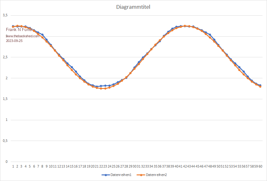 Blue is the actual measurement, red is a calculated sine wave. Frank |
||||
TassyJim Guru Joined: 07/08/2011 Location: AustraliaPosts: 6100 |
My toroidal transformer with a LM324 buffer and 1kHz low-pass filter (4.7k and 0.02uF) 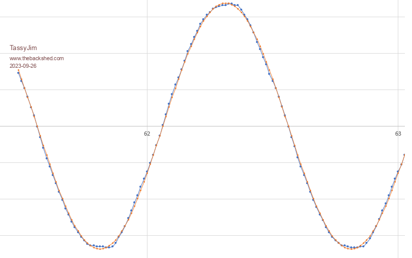 blue = sample orange = calculated This is with 4k sample frequency and 8bit resolution Jim VK7JH MMedit MMBasic Help |
||||
| Frank N. Furter Guru Joined: 28/05/2012 Location: GermanyPosts: 830 |
Your curve looks good - unfortunately a toroidal transformer is too big for my application... I'll try to scale my curve a bit better - currently I can't use the A/D converter to its full potential. Frank |
||||
| Volhout Guru Joined: 05/03/2018 Location: NetherlandsPosts: 4243 |
Hi Frank, I think this module ZMPT-101B should work. Of coarse the comment from the reviewer that R13 is a 1206 SMT resistor is correct. This resistor could cause problems, although not with heating. 1206 are either 125mW or 250mW. So the dissipation is within spec. The voltage however (<250V on 1206) is marginal. I would change that to a more capable resistor (or put 2x 390k in series, then 1206 would be OK). You will have to adapt the output voltage to the ADC range however. In the circuit I proposed this is also a point for attention. The LM358/LM324 will not drive any voltage below 0.8V (the output is not capable). When centered around 1.6V (mid ADC range) the maximum amplitude would be limitted to 1.6Vpp (effectively using only half the ADC range, that is 11 bits of 12 bits possible). When using a rail-rail opamp that will improve... The proposed common mode coil (39mH) would work fine. Volhout Edited 2023-09-26 22:43 by Volhout PicomiteVGA PETSCII ROBOTS |
||||
| Mixtel90 Guru Joined: 05/10/2019 Location: United KingdomPosts: 6798 |
I still like the idea of powering all the analogue detection and processing from the mains using a capacitive dropper and zener. Then use optcal isolation to send the data digitally to somewhere else - it could even be a fibre optic cable. It has a certain attraction for me. :) Mick Zilog Inside! nascom.info for Nascom & Gemini Preliminary MMBasic docs & my PCB designs |
||||
| Frank N. Furter Guru Joined: 28/05/2012 Location: GermanyPosts: 830 |
@Volhout: Thank you for your assessment! The layout of the module is horrible! The voltage gap between the GND plane and the voltage carrying side is much too small. But fortunately that's not what I'm concerned about - I'm only concerned about the principle... A ESP32 is to be used later - it is said to have a rather lousy ADC and to be usable only from 0.15V to 2.9V properly... Do you think an LV272 would be suitable? I have now changed R10 to 4K7 and adjusted the amplitude with the trim pot. This is the result: 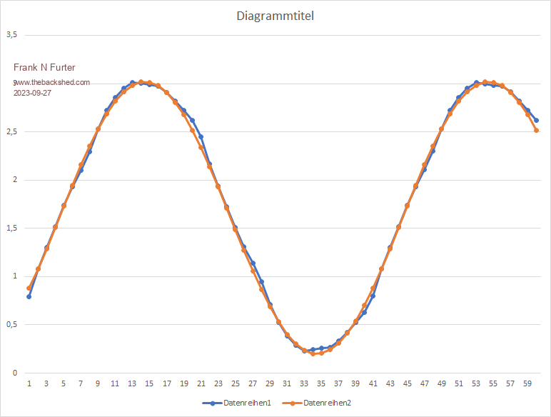 What do you think I need to change on the circuit to use the 744821039 choke? The internal resistance is only 3 ohms (for the ZMPT101B it is about 120 ohms) and I have too high a power loss if I would set the current to 820µA. I would rather let about 1.5mA flow through the choke. THANKS! Frank |
||||
TassyJim Guru Joined: 07/08/2011 Location: AustraliaPosts: 6100 |
I had a nearby lightning strike this morning which took out my mains power. This is what the pico captured: 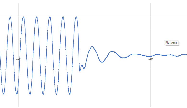 I am happy with the results. Still using a LM324 but have ordered a rail to rail op-amp to get a few more bits. The next part is to add the CTs and play with motor-start current. Jim VK7JH MMedit MMBasic Help |
||||
| Frank N. Furter Guru Joined: 28/05/2012 Location: GermanyPosts: 830 |
@TassyJim: Your curve looks really very good! I finally got around to experimenting a bit more. I have built the circuit of Volhout, but with a TLV272 operational amplifier, because I have no other available at the moment. I am surprised that my output does not oscillate around 1.6V but only around 1.1V although my reference voltage at IN+ of X1 is stable. If I increase the 220 Ohm resistor at X1, the amplitude will be higher, but the center line will sink even further?!? I used a 744821039 "common mode power line choke" from Würth with a 220K ohm at 230V... Am I doing something wrong or is it my TLV272? Would an LMV358 be a good choice? 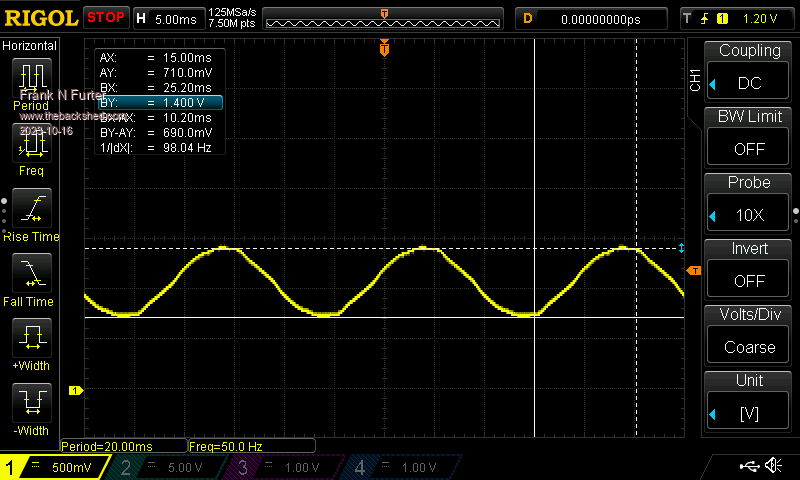 Frank |
||||
| phil99 Guru Joined: 11/02/2018 Location: AustraliaPosts: 2135 |
Some voltages to check. The non-inverting inputs of X1 and X2 should be V3 / 2, as should the output of X1. If those are correct the average output of X2 should also be V3 / 2 unless there is a resistive path to ground that should not be there. |
||||
| Volhout Guru Joined: 05/03/2018 Location: NetherlandsPosts: 4243 |
The TLV272 is rail to rail on the output, but not on the input. You could make it work if you power the opamp from 5V, not if you run it from 3.3v Volhout PicomiteVGA PETSCII ROBOTS |
||||
| Frank N. Furter Guru Joined: 28/05/2012 Location: GermanyPosts: 830 |
@phil99: I had also expected that. I have a 10K/4K7 voltage divider at 5V and thus get 1.6V. The output of X2 is also 1.6V. ...but the average output of X1 is lower - so far I could not find any error in my setup... It should also be at 1.6V??? I used a general purpose op amp board for the build: 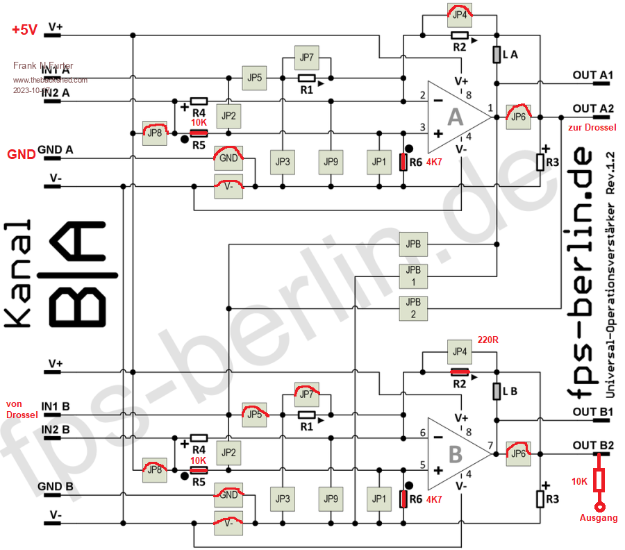 Have I set a wrong connection? @Volhout: I operate the TLV272 with 5V... Frank |
||||
| phil99 Guru Joined: 11/02/2018 Location: AustraliaPosts: 2135 |
You are using two voltage dividers for the non-inverting inputs. The smallest difference between them will be amplified. Connect the two non-inverting inputs together and see if that helps. A female Dupont wire from top of JP1 to top of other JP1 should work. |
||||
| Frank N. Furter Guru Joined: 28/05/2012 Location: GermanyPosts: 830 |
@phil99: THANK YOU VERY MUCH!!! That was it! ...as you can see, analog technology is not really my forte...  Frank |
||||
| Frank N. Furter Guru Joined: 28/05/2012 Location: GermanyPosts: 830 |
The image on the oscilloscope now looks like this: 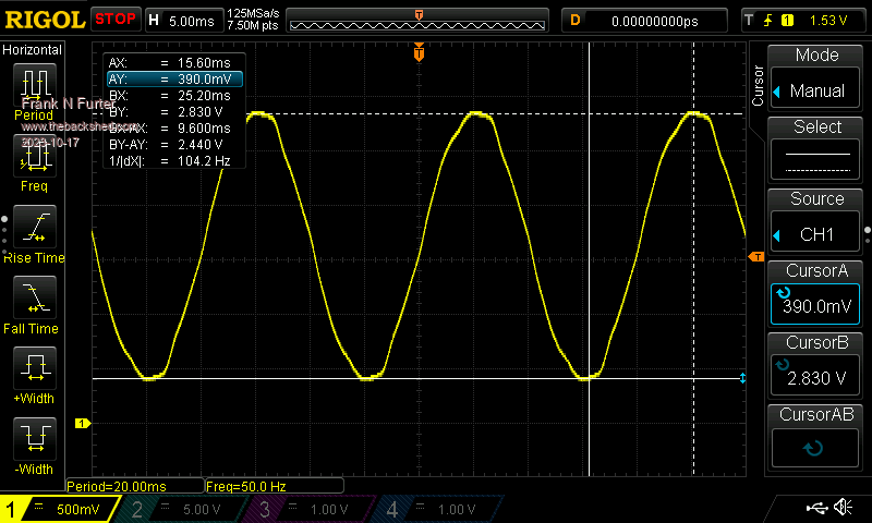 After digitization, things look even better: 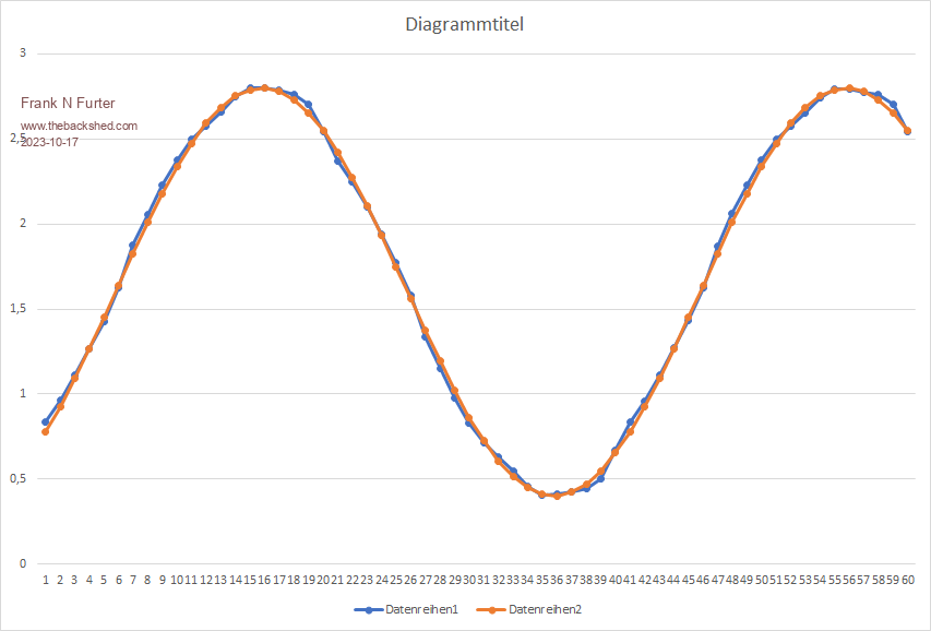 That's not so bad, is it? Frank |
||||