|

|
Forum Index : Microcontroller and PC projects : TinyBasic for the ATTiny85
| Author | Message | ||||
Grogster Admin Group Joined: 31/12/2012 Location: New ZealandPosts: 9308 |
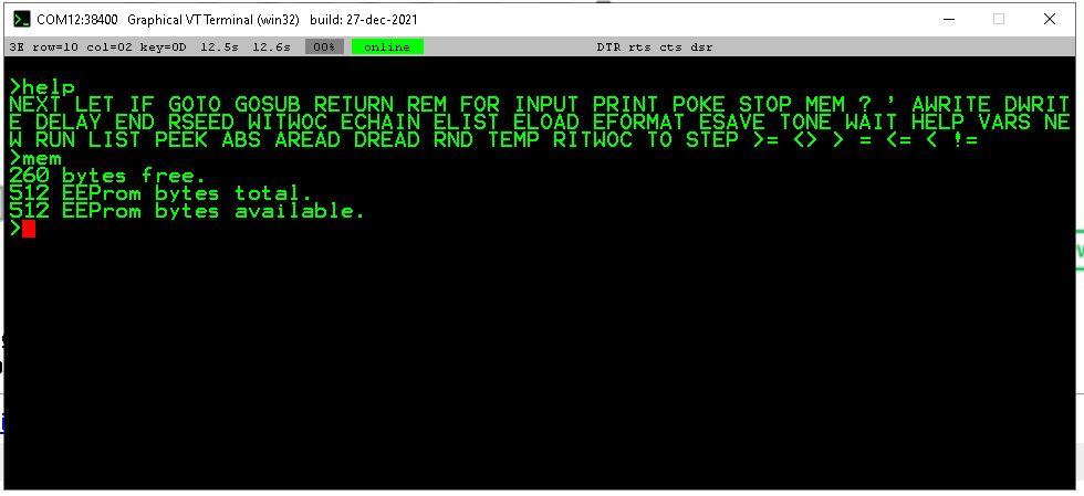
I would agree with that. In this project, every byte matters, so LET and REM seem to be somewhat memory gobblers.  ...unless the TinyBasic interpreter ignores REM and the ' mark, but I think I read that EVERY byte of the program is stored as ASCII bytes with no tokenization, so... Smoke makes things work. When the smoke gets out, it stops! |
||||
| matherp Guru Joined: 11/12/2012 Location: United KingdomPosts: 9126 |
Missing aread on pin 2 They cost 5 bytes of flash each - nothing else if you don't use them |
||||
| Volhout Guru Joined: 05/03/2018 Location: NetherlandsPosts: 4246 |
@Peter, I know you implemented I2C in the ATTINY. But the (very basic) way it is implemented, the basic code to talk to a I2C device consumes already half of the memory. Since most I2C devices support auto increment of registers, efficient basic code could make use of that. Not leaving much for any usefull coding. I know this proposal is not covering all I2C devices, but the few we could support may benefit from a format like this. WITWOC A,B,C,D,E (writes B,C,D,E to I2C device A, B could be a register pointer). RITWOC A,B,C,D (reads B,C,D from I2C device A). The start register pointer for read must be set in a separate IWRITE. Regards, Volhout Edited 2023-08-01 17:45 by Volhout PicomiteVGA PETSCII ROBOTS |
||||
| matherp Guru Joined: 11/12/2012 Location: United KingdomPosts: 9126 |
Not enough flash to parse the arguments |
||||
| Mixtel90 Guru Joined: 05/10/2019 Location: United KingdomPosts: 6798 |
The Singing Dog syndrome. The point is not that it sings badly but that it can sing at all. :) Mick Zilog Inside! nascom.info for Nascom & Gemini Preliminary MMBasic docs & my PCB designs |
||||
| Lou Senior Member Joined: 01/02/2014 Location: United StatesPosts: 229 |
Great words Mick, I like it !! And agree. Lou Microcontrollers - the other white meat |
||||
CircuitGizmos Guru Joined: 08/09/2011 Location: United StatesPosts: 1425 |
 Life has been messy. Many things have changed. I wish I had more time to be here. Thanks Grogs and Mixtel. Edited 2023-08-02 10:08 by CircuitGizmos Micromites and Maximites! - Beginning Maximite |
||||
| Mixtel90 Guru Joined: 05/10/2019 Location: United KingdomPosts: 6798 |
Oh, very artistic, Leonardo! :) Are you writing the manual by any chance? Mick Zilog Inside! nascom.info for Nascom & Gemini Preliminary MMBasic docs & my PCB designs |
||||
TassyJim Guru Joined: 07/08/2011 Location: AustraliaPosts: 6100 |
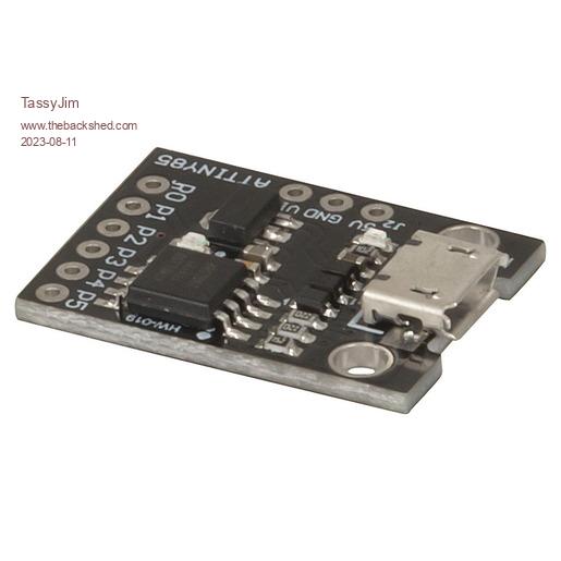
I have been playing 10 'kw\attiny 20 N = 16384 30 PRINT n* 2 40 n = n * 2 50 PRINT n 60 PRINT n-1 RUN --.)*( --.)*( 32767 OK > Trying to print 32768 gets interesting. As well as some loose chips, I purchased these boards  I didn't notice that there were only the 6 IO pins on the header. The 5V and GND are on the side making strip-board use not as friendly as I had hoped. The pins on the header are in PB order, not physical pin number which is not a problem, just untidy. The good news is, it has 78M05 regulator on board so powering from 12V is easy. The USB is not usable as data but handy for powering from a 5V plugpack. I think/hope I have stomped on all the bugs when using it with MMEdit. Jim VK7JH MMedit MMBasic Help |
||||
| pwillard Senior Member Joined: 07/06/2022 Location: United StatesPosts: 292 |
While not stripboard friendly, that looks like it's just the DIGISPARK layout so there are a lot of available daughterboards you can attach. digistump Edited 2023-08-11 19:52 by pwillard |
||||
| phil99 Guru Joined: 11/02/2018 Location: AustraliaPosts: 2136 |
However it might be ok on a breadboard, if the power pads line up with the power rails on the edge of the breadboard. |
||||
| Mixtel90 Guru Joined: 05/10/2019 Location: United KingdomPosts: 6798 |
They'll line up nicely if made from my favourite 0.6mm dia silver-plated copper wire. In fact, 2mm spaced connections are also breadboard-friendly when connected with that. Just bend to fit. :) It's also better for the breadboard than the usual 0.1" header pins, which are too thick for comfort. Mick Zilog Inside! nascom.info for Nascom & Gemini Preliminary MMBasic docs & my PCB designs |
||||
| OA47 Guru Joined: 11/04/2012 Location: AustraliaPosts: 926 |
Jim, I would like an idle current measurement at 12V when you get a chance. OA47 |
||||
TassyJim Guru Joined: 07/08/2011 Location: AustraliaPosts: 6100 |
25mA A lot of that is the linear regulator and there are two LEDs. One is connected to pin 6 which is the serial Tx so not any use. The other is power. If you are using them of restricted power, starting with the bare chip would be easiest. Jim VK7JH MMedit MMBasic Help |
||||
| OA47 Guru Joined: 11/04/2012 Location: AustraliaPosts: 926 |
Thanks Jim, I suppose restricting the Leds would possibly only gain 10-15 mA so I wouldn't class the module as low power. Thanks for the report. OA47 |
||||
| Mixtel90 Guru Joined: 05/10/2019 Location: United KingdomPosts: 6798 |
You may be able to snip through the power LED or its resistor. The TX LED is probably only used intermittently so it may not count. Even if the chip has a low power mode it's unlikely that any interpreter could use it. Mick Zilog Inside! nascom.info for Nascom & Gemini Preliminary MMBasic docs & my PCB designs |
||||
TassyJim Guru Joined: 07/08/2011 Location: AustraliaPosts: 6100 |
TTL serial idle is high so the LED is on most of the time. I wouldn't let the regulator supply much over 100mA when running from 12V. That is very close to a use I have in mind so I will be removing both LEDs. Jim VK7JH MMedit MMBasic Help |
||||
| Mixtel90 Guru Joined: 05/10/2019 Location: United KingdomPosts: 6798 |
That was a stupid way to drive a TX LED... :) Oh well, snip that one too. A standalone chip doesn't have it. Of course, a 78M05 has a quiescent current of about 6mA and you can't get rid of that. Mick Zilog Inside! nascom.info for Nascom & Gemini Preliminary MMBasic docs & my PCB designs |
||||
Grogster Admin Group Joined: 31/12/2012 Location: New ZealandPosts: 9308 |
Having had success in my other thread with the Atmel MEGA8, I programmed some of the tiny85 chips, but I cannot make them talk to me on the serial port not matter what. Should the be a pull-up resistor on RESET? I tried with and without, made no difference. Loopback test on my VCP adaptor works just fine, so the VCP is working, but the chips are not responding. 38k4 baud. I just used AVRDUDE to load the hex file and program it in, but perhaps I missed something else I was supposed to do? I'll start re-reading this thread from the beginning. Obviously, others have got their chips working, so it has to be something I am doing here.... EDIT: I think this is where my problem is, so I might need to go command-line for these - I used the AVRDUDE GUI instead. Yes, I forgot about setting the fuse for 16MHz. Once I did that, all systems are go!   Edited 2023-09-02 12:51 by Grogster Smoke makes things work. When the smoke gets out, it stops! |
||||
| disco4now Guru Joined: 18/12/2014 Location: AustraliaPosts: 897 |
Hi Grogs, I used AVRDUDE with Arduino as the programmer. Go back to the screen shot earlier in this post and you can se where I set the fuse to 0xF1. Use the read fuse button first, modify the one you want and then write them back, it does all three. Gerry Latest F4 Latest H7 |
||||