|

|
Forum Index : Microcontroller and PC projects : unreliable sd card reader?
| Author | Message | ||||
| Mixtel90 Guru Joined: 05/10/2019 Location: United KingdomPosts: 6798 |
This type has components on but I've never had a problem with them. I metered them out. There are 10K pullups on the data lines and about 32uF of decoupling capacitance on the 3V3 rail. For sheer luxury you can add an external 2R2 resistor. :) Mick Zilog Inside! nascom.info for Nascom & Gemini Preliminary MMBasic docs & my PCB designs |
||||
| hhtg1968 Senior Member Joined: 25/05/2023 Location: GermanyPosts: 123 |
i am still testing my picos and the sd card readers... i think one of the 5v readers is the evil reader. i have a pico with a 5v reader AND a level shifter (thanks to this forum) and all is well. but i have an pico with an 5v reader just connected to 5v-vsys at pico. many people here said that a level shifter is necessary, but it works, so i let it. from time to time there is a write error an from this time on this sd card is kind of corrupted. i will further have a look. perhaps this was the cause for all the trouble... |
||||
| stanleyella Guru Joined: 25/06/2022 Location: United KingdomPosts: 2129 |
5V sd card reader and if no on board reg will be 5V logic which is bad for pico. try running it from 3.3V. |
||||
| andreas Senior Member Joined: 07/12/2020 Location: GermanyPosts: 207 |
Hello Volhout, a wonderfull design! This is my version  -andreas |
||||
| Mixtel90 Guru Joined: 05/10/2019 Location: United KingdomPosts: 6798 |
The problem is with the Arduino system that these boards are targeted at. All SD cards are 3V3. There are no 5V ones so they can't be used as-is on an Arduino. The Arduino only has a 5V supply, so the boards helpfully include a 3V3 LDO regulator and a level shifter or, as a minimum, series resistors in the signal lines to hopefully protect the SD card against the 5V signals on the Arduino pins. When you put one of the Arduino SDcard modules on a 3V3 system you have two problems. The regulator is now being fed with 3V3 so, if you are lucky, it will switch on and give you a wobbly 3V or so as it can't regulate properly. If you are unlucky it won't switch on at all and you'll get nothing out. The series resistors are now causing a problem the other way, a high level on the 3V3 pins of a Pico is being reduced by them, sometimes to the point where they aren't quite being recognised as a logic 1. Basically, if an adapter is being advertised as "for Arduino" then investigate it closely before spending any money. You don't want a regulator or anything that looks like a level shifter. Mick Zilog Inside! nascom.info for Nascom & Gemini Preliminary MMBasic docs & my PCB designs |
||||
| stanleyella Guru Joined: 25/06/2022 Location: United KingdomPosts: 2129 |
Typing option list into teraterm I get > option list PicoMite MMBasic Version 5.07.07 OPTION SYSTEM SPI GP10,GP11,GP28 OPTION HEARTBEAT OFF OPTION LCDPANEL ST7735S, LANDSCAPE,GP8,GP12,GP9,GP25 OPTION AUDIO GP0,GP1, ON PWM CHANNEL 0 > The manual says OPTION LCDPANEL ST7735S, OR, DC, RESET, CS so why do I have 4 gp pins in option list?? edit Is gp25 a backlight? edit if it is do I use option reset and start over and do I use clk,mosi,miso the lcd uses and a gp pin for cs using option sdcard gp ? never done this before. sd card readers on ili9341 on a plate in the manual with pictures. Edited 2023-06-21 04:10 by stanleyella |
||||
| Mixtel90 Guru Joined: 05/10/2019 Location: United KingdomPosts: 6798 |
Because you are using the little Waveshare display. The GP25 that's shown is the backlight option. It's a few pages on from the OPTION LCDPANEL list in my (out of date) manual. Mick Zilog Inside! nascom.info for Nascom & Gemini Preliminary MMBasic docs & my PCB designs |
||||
| stanleyella Guru Joined: 25/06/2022 Location: United KingdomPosts: 2129 |
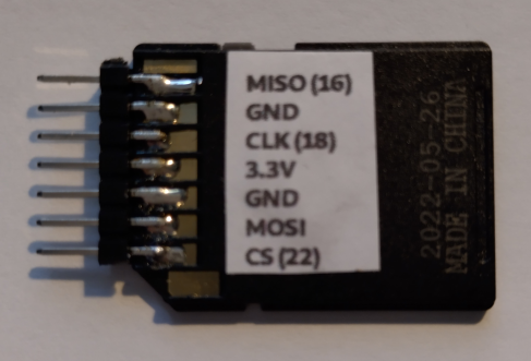
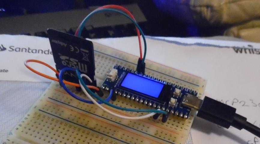
wired the adapter and 16mb card but typing files in teraterm shows > files A:/ <DIR> . <DIR> .. 00:00 01-01-2000 4 bootcount 2 directories, 1 file, 712704 bytes free > tried to change to "B:" command not recognises error. I never used sd card so how to test on non vga. using option sdcard gp16  |
||||
| Mixtel90 Guru Joined: 05/10/2019 Location: United KingdomPosts: 6798 |
First, make sure that the pins you are using aren't being used by something else on that board. You can use any pins for a SDcard if you specify them all. You can use the system SPI pins if you like, but with a CS pin that isn't shared with anything else. You won't see the file listing on the LCD normally, only on the console. After that just enter FILES. If there's no card in it'll tell you, otherwise you should get a listing. Cards have to be formatted to FAT16 or FAT32 - Not NTFS, which is what Windows always wants to use by default. They can be up to 32GB. Mick Zilog Inside! nascom.info for Nascom & Gemini Preliminary MMBasic docs & my PCB designs |
||||
| stanleyella Guru Joined: 25/06/2022 Location: United KingdomPosts: 2129 |
Thanks again Mick, sd csard adaptor not working, files show A:. I think choosing GP16 as CS was a mistake,should have used gp22. How to reset option sdcard gp16 please. sorry to be a pain, it's new stuff to me. |
||||
| Mixtel90 Guru Joined: 05/10/2019 Location: United KingdomPosts: 6798 |
You'll have to clear the setting with OPTION SDCARD DISABLE then put the new options in. The display is using GP8-12 and GP25 so I'd have thought you'd have been ok with GP16. Make sure you've followed the manual with regard to how to connect it. If you have put it on System SPI then you only need OPTION SDCARD GP16. If not you have to specify all the pins. I'm not sure which version of MMBasic you are using. Try using DRIVE B instead of B: to change drives. EDIT: To use System SPI pins: OPTION SYSTEM SPI GP10,GP11,GP28 Connect MISO to GP28, MOSI to GP11, SCK to GP10, CE to GP16 Edited 2023-06-22 03:09 by Mixtel90 Mick Zilog Inside! nascom.info for Nascom & Gemini Preliminary MMBasic docs & my PCB designs |
||||
| stanleyella Guru Joined: 25/06/2022 Location: United KingdomPosts: 2129 |
Maybe my soldering is carp. I tried not sharing spi with display and used optin sdcard but no joy. can't think of anything else. The 4GB has a file.bas but just shows drive A: I'll solder another. yawn :) Ta for helping though Mick :) > option list PicoMite MMBasic Version 5.07.07 OPTION SYSTEM SPI GP10,GP11,GP28 OPTION LCDPANEL ST7735S, RLANDSCAPE,GP8,GP12,GP9 OPTION SDCARD GP22, GP18, GP19, GP16 > |
||||
| JohnS Guru Joined: 18/11/2011 Location: United KingdomPosts: 3804 |
Is A: the flash and the SD card B: ? John |
||||
| Mixtel90 Guru Joined: 05/10/2019 Location: United KingdomPosts: 6798 |
If you are specifying all the pins the sequence is OPTION SDCARD CS, SCK, MOSI, MISO These have to line up with the card connections, obviously. In order from the chamfered corner of the holder the order is 9,1,2,3,4,5,6,7,8 9: no connection 1: CS 2: MOSI 3: GND 4: 3V3 5: SCK 6: GND 7: MISO 8: no connection Note that there are two GND connections (they may be linked elsewhere but it does no harm to connect both). Better check your wire connections to the socket. Maybe try a different set of holes on your breadboard too. Your soldering doesn't look bad to me. Are you certain that the card is formatted FAT16 or FAT32? If you just put it into a windows machine and format it it will probably end up as NTFS and it won't work. @ John Yes. :) Edited 2023-06-22 05:51 by Mixtel90 Mick Zilog Inside! nascom.info for Nascom & Gemini Preliminary MMBasic docs & my PCB designs |
||||
| stanleyella Guru Joined: 25/06/2022 Location: United KingdomPosts: 2129 |
The card is fat 32 with a .bas file. The card was wired correct for sharing the spi with the display, just added option sdcard gp16 then reset and used gp22 instead. Then tried option reset and set up again but OPTION SDCARD GP22, GP18, GP19, GP16 No pins used twice Still no joy ie files lists A: Now the waveshare 2040 lcd displays any running program for a second then blank screen then displays a second repeating 4e4. I'll reflash hardware but think I messed it, never seen this :( want to see a video? edit I'm not using lcd gp25 backlight, could that be the once a second blanking. let you know Edited 2023-06-22 06:58 by stanleyella |
||||
| Mixtel90 Guru Joined: 05/10/2019 Location: United KingdomPosts: 6798 |
Never seen anything like that. See if a re-flash fixes it. I assume you checked with a meter for shorted pins on the SDcard socket? There could be heat damaged insulation where you can't see it, I suppose. Edited 2023-06-22 06:57 by Mixtel90 Mick Zilog Inside! nascom.info for Nascom & Gemini Preliminary MMBasic docs & my PCB designs |
||||
| stanleyella Guru Joined: 25/06/2022 Location: United KingdomPosts: 2129 |
Hi Mick. The every second blanking WAS not using gp25 backlight. Me smug mr spock :) handy tip for waveshare 2040 lcd users sdcard adaptor no shorts but maybe no connection to card? not meant for soldering,try again. the backlight pin must default on if not set up Edited 2023-06-22 07:33 by stanleyella |
||||
| matherp Guru Joined: 11/12/2012 Location: United KingdomPosts: 9129 |
files "B:/" |
||||
| stanleyella Guru Joined: 25/06/2022 Location: United KingdomPosts: 2129 |
tried drives B: and when command worked files said no sdcard :) I solder another,got loads. thanks |
||||
| stanleyella Guru Joined: 25/06/2022 Location: United KingdomPosts: 2129 |
Melted 2 more adaptors. Buy one that works. spend £5, less haddock,I give up. |
||||