|

|
Forum Index : Microcontroller and PC projects : PicoMite: Controllers ... again ;-)
| Author | Message | ||||
| Hawk Senior Member Joined: 15/07/2021 Location: AustraliaPosts: 141 |
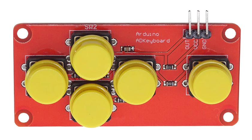
You could save a whole lot of pins if you just used one of these.  I requires just one analogue line.  |
||||
| Mixtel90 Guru Joined: 05/10/2019 Location: United KingdomPosts: 6808 |
Oh, there's all sorts of ways to do it. You still can't beat 8 controllers, each that can be used as analogue or digital (like the Xbox) and with over 8 digital inputs all on one I2C port. :) Ok, you need a PicoMite in each controller if you want the analogue function. No joystick or controller reads as fast as the switched Atari stick wired to GP pins though. Oh, and yes - you can use three of those analogue button thingies on the PicoGAME already. :) Mick Zilog Inside! nascom.info for Nascom & Gemini Preliminary MMBasic docs & my PCB designs |
||||
| stanleyella Guru Joined: 25/06/2022 Location: United KingdomPosts: 2130 |
https://www.ebay.co.uk/itm/334847975412? @Hawk- do they work like left and right and fire tested for in mmbasic software? £3, why get a soldering iron out? |
||||
| Mixtel90 Guru Joined: 05/10/2019 Location: United KingdomPosts: 6808 |
You just get a different percentage of VCC on the OUT pin depending on which button is pressed. You can either keep sampling an ADC port or, if you want to use more than one, you can get MMBasic to run a round robin sample on how ever many ADC pins you want to use. The exact voltages you get will depend on VCC. Obviously they will be lower on a 3V3 system than on a 5V system. Mick Zilog Inside! nascom.info for Nascom & Gemini Preliminary MMBasic docs & my PCB designs |
||||
| stanleyella Guru Joined: 25/06/2022 Location: United KingdomPosts: 2130 |
will order 2. will see. can always rewire for 5 ports. if it's meant for 5V then less accuracy at 3V. only £3 though. There's discussion about this and all the different adc values and resistor values. but I ordered the boards. which will be tiny and easier than wiring buttons. not a gamepad but would do as although touch screen "works", it's not the same as buttons Edited 2023-04-28 06:16 by stanleyella |
||||
| stanleyella Guru Joined: 25/06/2022 Location: United KingdomPosts: 2130 |
adc= up or + fire down or + fire left or + fire right or + fire left + up or + fire left + down or + fire right+ up or + fire right + down or + fire just using these combinations is 16 values. Waiting until board arrives to see if the hardware works |
||||
| Mixtel90 Guru Joined: 05/10/2019 Location: United KingdomPosts: 6808 |
There are only 2 ways to wire them really. A switched ladder is easy but the last button in the chain overrides the others. Separate binary loaded resistors (1,2,4,8,16), one for each button, let you detect which buttons have been pressed. e.g. reading 5 will indicate that buttons 1 and 4 have been pressed. That's the best way but you need closer tolerance resistors. In both cases you have to compare the voltage value in a window as the resistors may not be well matched. Mick Zilog Inside! nascom.info for Nascom & Gemini Preliminary MMBasic docs & my PCB designs |
||||
| stanleyella Guru Joined: 25/06/2022 Location: United KingdomPosts: 2130 |
A lot of cases and envelopes but must do something or it not be sold... eright :) When boards arrive in May, I'll test, I guess I could now with pots.. but can't be |
||||
| phil99 Guru Joined: 11/02/2018 Location: AustraliaPosts: 2140 |
Looking at the photos of those controllers from various manufacturers what I see is: All buttons switch OUT to GND via a series resistor except UP which goes direct from OUT to GND. The series resistors are. R2 330R LEFT R3 560R or 620R DOWN R4 1K RIGHT R5 3K3 FIRE C1 (100n?) from OUT to GND R1 (1k or 2k or 10k or 01C whatever that is?) from Vcc to OUT. To standardize the value of R1 put your desired value on your PCB and don't connect Vcc to the controller just OUT and GND. 1k seems like a good value. The approximate output voltages would be:- UP 0.0 LEFT 0.82 DOWN 1.26 RIGHT 1.65 FIRE 2.53 None 3.3 Select Case with values half way between those should be ok. UP < O.4 LEFT > 0.4 and < 1.0 DOWN > 1.0 and < 1.4 RIGHT > 1.4 and < 2.0 FIRE > 2.0 and < 2.5 None > 3.0 Edited 2023-04-28 13:51 by phil99 |
||||
| stanleyella Guru Joined: 25/06/2022 Location: United KingdomPosts: 2130 |
Nice phil99 , I got to wait for devices to arrive, cheap means long postage. I run my boards from 3.3V linear reg with 3.3v enable grounded. I wanted a "clean" 3.3V ref. This has been done before for a-d. |
||||
| phil99 Guru Joined: 11/02/2018 Location: AustraliaPosts: 2140 |
Spotted a mistake. Change FIRE to < 3. UP < O.4 LEFT > 0.4 and LEFT < 1.0 DOWN > 1.0 and DOWN < 1.4 RIGHT > 1.4 and RIGHT < 2.0 FIRE > 2.0 and FIRE < 3.0 None > 3.0 These could have been designed to allow diagonal moves. If the fire button was the one that goes straight from OUT to ground the series resistors for the four direction buttons could use binary sequence values. Then more than one button could be pressed at the same time and be correctly decoded. Edited 2023-04-29 09:27 by phil99 |
||||