
|

|
Forum Index : Solar : Deciding if I should build this solar heater
| Author | Message | ||||
| rogerdw Guru Joined: 22/10/2019 Location: AustraliaPosts: 852 |
Finally picked up all the tubes and frames today. 10 tubes per box for most and 12 in two boxes. A couple with broken glass sound, so a few fatalities. But still about 140 tubes. Were also 4 complete frames. Bit like an Ikea project except no instructions ... and a handful of reflector panels that I assume go behind the tubes for a bit of reflective light. Biggest surprise was that the frames are designed for 18 tubes. Most of the ones I've ever seen were either 10, 20 or 30 tube sets. I'm especially happy that there's some sets of rubber seals for the top of the tubes and the plastic inserts to protect the nipple on the bottom of the tubes. And I'm sure I can make use of some of the other bits. 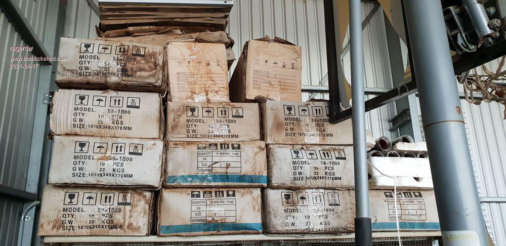 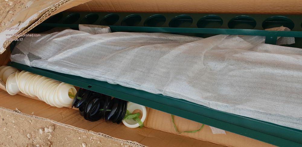 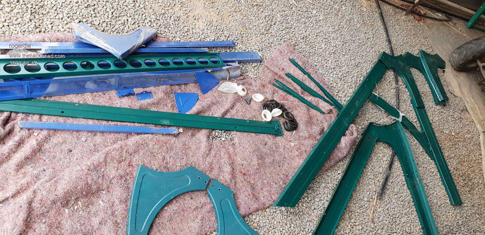 Cheers, Roger |
||||
| Murphy's friend Guru Joined: 04/10/2019 Location: AustraliaPosts: 648 |
#3 looks the best choice to me but I would push the cold air in with the fan - they last longer when not running in hot air. You would need to keep the cold tubes concentric inside the glass tubes without restricting the air flow, that might be tricky. If there are a lot of evac tubes then the cold air in would have to be in several places of the manifold or the last in line gets b/a pressure. Try it with alu tubes, they are cheap enough and come in 4m lengths. If the cold air manifold is made from a square plywood box you could have the tube side thick enough for a press in fit for them, just need a sharp drill to drill a clean hole. |
||||
| rogerdw Guru Joined: 22/10/2019 Location: AustraliaPosts: 852 |
Mmm ... that does make sense, though I do recall reading that it is better to suck the air out than try and blow it in. Will need more research there. I did wonder about winding some spring wire tightly around the tube ... then bending it out to a larger circle ... at the inside diameter of the glass tube. You are correct in that it will reduce the air flow but if I keep it fairly thin it shouldn't be too bad. Maybe some thick piano wire ... that's pretty springy and strong. Yeah, I've been trying to work out if the inner manifold needs to be tapered, but don't really know. I initially drew it with all the centre pipes being brought out individually to the inlet ... but that was going to be very messy as well as mechanically difficult to build ... not to mention the extra expense. My first idea was to use plywood for both manifolds and make the centre tubes a press fit ... which would have been perfectly ok under the eaves ... ... but it's looking like I'll need to lay this on the roof because of lack of space on the side wall where I initially wanted to put it. That means at least a metal outer section so may need to use metal for both. I may have to sweat in a row of short stubs that my centre pipes can be pressed into once the centre manifold is slid into the outer manifold. Maybe even a smear of silicone first so they don't rattle loose and slide to the bottom of the glass tubes. Cheers, Roger |
||||
| Warpspeed Guru Joined: 09/08/2007 Location: AustraliaPosts: 4406 |
I will raise my hand for #3 as well. Work out the cross sectional areas of inner and outer flow paths and keep them the same for minimum overall pressure drop. Inside pipe should in theory be about 0.7 the diameter of the outer pipe. We don't want the thing to get really hot !! We want to extract as much heat as possible without the temperature rising by very much. Keeping the inner tube centered just needs a "spider" at the far end with three or more thin legs. I would use copper pipe for both inner and outer and assemble the whole thing independently if it was used for water, even mains pressure water. If it was for air, I think I would prefer thin aluminium tubing. Then the whole thing could just slide inside the outer glass hardware. The outer tube surface should be black and not touch the glass. A couple of thin O rings would be a simple way to achieve separation without taking up much space. Cheers, Tony. |
||||
| Davo99 Guru Joined: 03/06/2019 Location: AustraliaPosts: 1578 |
Me too. Also the most difficult to engineer. |
||||
| rogerdw Guru Joined: 22/10/2019 Location: AustraliaPosts: 852 |
I had come to that conclusion as well. Of course the overall diameter of the manifolds will depend on how many evac tubes I use. The inner down tubes ideally will be ~30mm diameter. The evac tube ID is 43.5mm. Was planning on 30 for some reason ... but now that I see my frames suit 18, I'm not sure if I'll go for 18 or 36. Though the only thing I really want to use is the bottom tube support piece that already has all the holes cut along with matching plastic inserts. 30 would fit within 2.4 meters but 36 is well over that ... and so could make it harder to find material to make my manifolds ... depending of course how they're constructed. Yes, understood True, in fact because the tubes will be nearly horizontal, I may get away with just two legs. A piece of spring wire wrapped around the tube and with the two legs at 4 o'clock and 8 o'clock. At this stage I'm going for an air heater, so I won't confuse myself with variations for water. Maybe later if the air one works well I might try some water heating. Ahh ... ok. It's taken me a while to work out what you meant (I think). So you're suggesting having thin aluminium tubing spigots out the side of the outer manifold ... then sliding the evac tube over the outside of them, with a couple o-rings for sealing ??? It took me a while to come to that as I kept thinking the outside of the glass has to fit inside a hole on the side of the manifold. One big advantage of this way is there is no restiction to the inside diameter for air to flow through the mouth, which would be created with a tube and an o-ring. Also don't need to weld on a heap of spigots ... ... but then still have to deal with cutting a heap of 60mm holes and sealing between them and the tubes. One way I had considered to do that, was to use a length of C-section. Use a hole saw to cut all my holes oversize by about 7 or 8mm ... screw it into place on the face of the manifold ... ... then fit temporary plugs in the holes just a few mm undersize ... ... finally fill full of spray foam. When it's set, pull out the plugs and I'll have tight fitting foam seals an inch and a half deep to plug my evac tubes into. Air tight and shock absorbing. Maybe I'm dreaming or have forgotten a few vital facts ... not sure.  So while I initially was looking at using marine ply for a system under the eaves ... now I'm looking at metal air conditioner ducting to create my two main manifolds. Gotta go check out the local scrap yards to see what's lying around. Probably the most difficult task I can see is to have to fit 30 short pieces of tube (to fit the centre pipes into) ... onto a 7 or 8 inch thin wall inner metal tube, the inner cold air manifold. Cheers, Roger |
||||
| Warpspeed Guru Joined: 09/08/2007 Location: AustraliaPosts: 4406 |
This is how I would do it (not to scale): 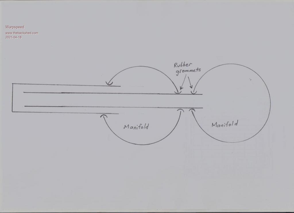 The grommets could be home made from standard soft rubber extrusion, cut, and superglued into a circle. The outer tube would be painted black, and the glass vacuum tubes would slip over the outside of the larger tube. Edited 2021-04-18 12:54 by Warpspeed Cheers, Tony. |
||||
| rogerdw Guru Joined: 22/10/2019 Location: AustraliaPosts: 852 |
That is cool, I like it. And so much easier too. No welding. Clearly more than one way to skin a cat.  Actually the more I think about it the more I like it. Thanks very much Tony. Cheers, Roger |
||||
| rogerdw Guru Joined: 22/10/2019 Location: AustraliaPosts: 852 |
So I drew it out to help with my understanding of how it might physically go together and have a few questions. What are your ideas on the fan ... should it push or pull? And would it matter if the inlet and outlet were at the same end? And any thoughts on summer time ... I guess it'll need to be covered or it will be sitting on the roof getting red hot but not going anywhere. Edit: Reduced size of graphic. 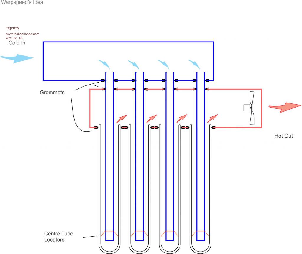 Edited 2021-04-18 14:32 by rogerdw Cheers, Roger |
||||
| Warpspeed Guru Joined: 09/08/2007 Location: AustraliaPosts: 4406 |
Your drawing looks a lot better than mine !! Fans should always push if you have a choice. Fans that pull work in less dense air, especially if its hot, and may cavitate more easily. Usually a reversed return is the best engineering solution, especially if the manifolds are small or excessively long. But if most of the pressure drop is in the pickup tubes, and the manifolds are a decent flow size, air distribution should be pretty even. The outside of the pickup tubes should be dull black for max heat absorption. I would use VHT exhaust pipe paint, its dull black and works to 1,500 Celsius. Should last for years. https://www.ebay.com.au/itm/VHT-Flame-Proof-Flat-Black-Header-Exhaust-Paint-SP102/254517145459?epid=244328521&hash=item3b42676f73:g:cLQAAOSwrSpemFKG Don't know about summer, but beware of thermal expansion. Anything rubber may have a short life, may need to rethink that part. Cheers, Tony. |
||||
| rogerdw Guru Joined: 22/10/2019 Location: AustraliaPosts: 852 |
Haha, thanks. Okay that is easily fixed. Done. Had to google 'reversed return' to work out what it was. Never heard of it before. So if I understood it correctly, it would still pay to have the inlet one side and outlet on the other ... last in, first out. That I do understand. Yes, that may be a bit of problem, though if the concept works well I will be happy to invest more time and effort into it. A comment you made earlier about not wanting the whole assembly to get too hot and to draw out the heat before it rises too high, has me wondering if I'd get away with fairly thick pvc pipe for my manifolds ... at least for my prototype. Certainly with the new design I should be able to get away with pvc for the cold one ... but perhaps even for the hot side. Depending on how many evac tubes I use, I could use either 6 inch or 8 inch tubing. Cheers, Roger |
||||
| Warpspeed Guru Joined: 09/08/2007 Location: AustraliaPosts: 4406 |
Sorry about the "reversed return" its a bit of engineering jargon. But as you know it just means the "to" manifold goes one way, and the "return" manifold reverses back to the starting place, so in and out are at the same end. Should work fine with inlet and outlet at the same end, providing the manifold is generous, and not too long. When I was involved with State Government solar thermal projects many years ago, the rule of thumb there with PVC pipework is that anything that runs continuously at 80 Celsius, and the pipework turns into flaccid spaghetti. Sags like a limp noodle. No problem in winter with the blower going. In summer there may be issues. My own gut instinct suggests that the pickup tubes and manifold should be metal. But beyond the manifold PVC should be quite adequate. Even if you fire it up in summer, the temperature extreme will quickly fall back before the pipework melts. That all assumes sufficiently high airflow. This will all work a lot better with a very high volume of warm air, rather than a low volume of very hot air. When it heat soaks in summer with the fan off, temperatures could get extremely high, but not beyond the manifold with the fan off. Edited 2021-04-18 17:57 by Warpspeed Cheers, Tony. |
||||
| rogerdw Guru Joined: 22/10/2019 Location: AustraliaPosts: 852 |
Mmm ... now I'm confused. I read up on it and was left with the impression that a reversed return was ... So from that explanation it would be best with in and out at opposite ends? Unless I'm still reading it wrong.  That's very helpful thanks. I have seen 70 degrees C at 5pm on a fairly average day ... so if we happened to cop a bright sunny winter's afternoon, it would definitely go much higher. Again, on a fairly mild afternoon with just a bit of sun it's reached 150 C, so no point messing with plastic at all by the looks. Yep, ok. Looks like metal manifolds and down tubes. Ducting would probably be some insulated flexible aircon ducting. And then some decent temperature monitoring so the fan is turned on and off appropriately. Cheers, Roger |
||||
| Warpspeed Guru Joined: 09/08/2007 Location: AustraliaPosts: 4406 |
Here you go, Google image, reverse return. Lots of pictures: https://www.google.com/search?q=reverse+return&hl=en&gl=ar&tbm=isch&source=hp&biw=1637&bih=920&ei=sSR8YKStFpeQ4-EPrI-E8Ao&oq=reverse+return&gs_lcp=CgNpbWcQAzICCAAyAggAMgIIADICCAAyAggAMgIIADICCAAyAggAMgIIADICCAA6CAgAELEDEIMBOgUIABCxA1D0HVizPGDyP2gAcAB4AIABwQGIAfUOkgEEMC4xNJgBAKABAaoBC2d3cy13aXotaW1n&sclient=img&ved=0ahUKEwjkyY235IfwAhUXyDgGHawHAa4Q4dUDCAY&uact=5 This is the classic layout, two manifolds and the inlet and outlet are at opposite ends. 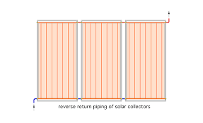 Edited 2021-04-18 22:36 by Warpspeed Cheers, Tony. |
||||
| Solar Mike Guru Joined: 08/02/2015 Location: New ZealandPosts: 1138 |
I use this method on my array of solar hot water panels, it allows a more even flow rate through the tubes in the center, where otherwise the flow may stop and stagnate. Mike |
||||
| rogerdw Guru Joined: 22/10/2019 Location: AustraliaPosts: 852 |
Thanks Tony, the pictures help. I can be a little slow at times.  Still, better to ask than carry on the wrong way. And thanks Mike as well. Cheers, Roger |
||||
| rogerdw Guru Joined: 22/10/2019 Location: AustraliaPosts: 852 |
I know I said I am building an air heater and not a water heater ... but bear with me. I came across this image this morning and it looks very familiar. 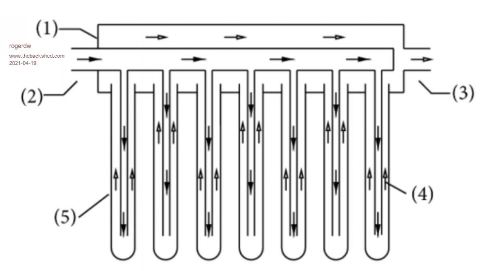 It comes from a paper where experiments were made comparing this 'down tube' method with the very basic (no heat tubes) system ... ... where the evac tubes just plug in the bottom of a tank full of water and thermocycle as best they can. Turns out in their conclusion ... that with down pipes, they get a whopping 5% extra heat output!!! Also interesting to see that for an internal diameter of 47mm ... the best down tube size turned out to be 32mm Very close to Tony's suggested 70% diameter ... which provides the same cross sectional area in as out. So the point of bringing this up, is that with air being very similar to water ... is it possible that I may not need downpipes for my air heating system either? I'll paste an extract below to save trying to find it ... Cheers, Roger |
||||
| Warpspeed Guru Joined: 09/08/2007 Location: AustraliaPosts: 4406 |
Downpipes perform one EXTREMELY important function, they must be black to absorb heat that is then transferred by conduction to the "fluid". A clear glass tube full of air or water will do almost nothing. Radiant sunlight flows through the entire atmosphere giving up almost no heat. It will also flow straight through clear glass or water. You must have a black heat absorber in the system for it to work at all. Sure, a clear glass jar left out in the sun will get hot. But try painting one black, and it will get a LOT hotter. Cheers, Tony. |
||||
| rogerdw Guru Joined: 22/10/2019 Location: AustraliaPosts: 852 |
Yes, understood, but the tubes do have a black coating that absorbs the heat already built in. In fact I wonder if any light would actually reach a downtube. Certainly heat could radiate to it from the hot black inner glass surface, but it is virtually opaque. When you poke your fingers inside a tube that's been in the sun, it can feel warm ... but if you touch the inner surface it can be extremely hot ... like I've seen up to 200 degrees C. Cheers, Roger |
||||
| Solar Mike Guru Joined: 08/02/2015 Location: New ZealandPosts: 1138 |
Your internal down pipes convey the cooler air to the bottom of the tube, then it warms up also creating extra turbulence as it rises gaining heat from the black hot surface of the larger outer tube. This turbulence caused by the incoming air pressure is important, as it raises the efficiency of heat transfer, by disrupting any laminar flow to the air as it moves up the tube, without the extra down tubes there will be little air turbulence and decreasing as one goes down from the top to near stagnation at the bottom. Painting your down tubes wont make much difference to the heat output, as there should be sufficient air flow from your fan to have only a small differential delta between the incoming and outgoing air. High delta's will be inefficient. Cheers Mike |
||||